
Battery pack assembly

A battery pack and assembly technology, applied in the field of new energy vehicles, can solve the problems of unreasonable space layout, reduced power layout, unfavorable vehicle layout and on-site process installation, so as to achieve reasonable space structure setting and reduce wiring harness Installation and, reduce the effect of the assembly process

Pending Publication Date: 2020-07-17
DFSK MOTOR LTD CHONGQING BRANCH CO
View PDF0 Cites 6 Cited by
  • Summary
  • Abstract
  • Description
  • Claims
  • Application Information

AI Technical Summary

Problems solved by technology

For the four-wheel drive solution, the above technical solution is not conducive to the layout of the vehicle and the installation of on-site technology: the battery pack only has one set of high-current discharge output, no matter which direction the output interface is installed in the battery pack, it will inevitably involve at least one set of high-current cables Installation from front to back (or from back to front) will involve the following disadvantages: the cables need to be routed from the inside of the car (occupies the space in the car, involves cables passing through the body sheet metal parts, there are risks of water leakage and electrical safety, cable installation Difficult), or the wiring in the middle channel of the chassis (occupies the space in the middle channel, difficult to install, and the cable is easy to interfere with the battery pack cover, resulting in electrical safety risks), or the wiring on both sides of the chassis (will occupy the space of the battery pack, reduce the power layout, Difficult to install); all will involve space occupation, inconvenient installation and safety issues
This solution has the following two defects: 1. Incomplete charging facilities, 2. Insufficient driving range, and 3. Unreasonable space layout. From the perspective of the whole vehicle, increasing the driving range will directly increase the competition of the core of the vehicle. force

Method used


Image

  • Battery pack assembly
  • Battery pack assembly
  • Battery pack assembly

Examples


Embodiment Construction

[0029] In order to make the purpose, technical solutions and advantages of the present invention clearer, the technical solutions in the embodiments of the present invention will be clearly and completely described below in conjunction with the accompanying drawings in the embodiments of the present invention. Obviously, the described embodiments are only Some, but not all, embodiments of the invention. Based on the embodiments of the present invention, all other embodiments obtained by persons of ordinary skill in the art without making creative efforts belong to the protection scope of the present invention.

[0030] It should be noted that, the descriptions of the present invention on directions such as "below", "front", "rear", "left", and "right" are all defined based on the orientation or positional relationship shown in the drawings, and only In order to facilitate the description of the present invention and simplify the description, it does not indicate or imply that ...


PUM

PropertyMeasurementUnit
sizeaaaaaaaaaa
sizeaaaaaaaaaa

Abstract

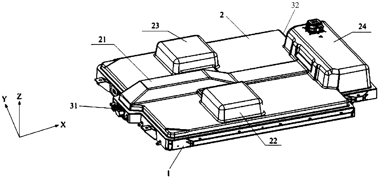
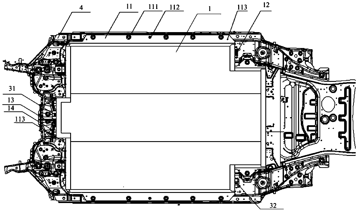
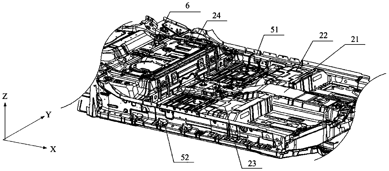
The invention relates to the technical field of new energy vehicles, in particular to a battery pack assembly. The battery pack assembly comprises a battery pack assembly box body and a battery module, and the battery pack box body comprises a bottom plate and an upper cover. The battery pack assembly is characterized in that the upper cover is provided with a middle channel convex hull along theX direction, the left side and the right side of the middle channel convex hull are provided with a left front convex hull arranged to correspond to a main driver seat and a right front convex hull arranged to correspond to an auxiliary driver seat respectively, a rear convex hull corresponding to the rear row of seats is arranged behind the middle channel convex hull and along the Y direction, and the battery pack assembly box body is provided with two high-voltage output interfaces used for being connected with two external high-voltage distribution box assemblies.

Description

technical field [0001] The invention relates to the technical field of new energy vehicles, in particular to a battery pack assembly. Background technique [0002] Under the general environment of environmental protection and energy security, with the strong support of national policies, new energy vehicles have developed rapidly in recent years, and the number of new energy vehicles is in a stage of rapid increase. However, in recent years, safety accidents related to new energy vehicles have occurred continuously, hindering the development of new energy vehicles. It is true that the development of new energy vehicles has not been smooth sailing. As a product related to personal safety, property safety, and environmental safety, it is necessary to ensure the safety of the entire vehicle from multiple angles, especially the high-voltage safety of the entire vehicle. The battery pack assembly is the core component of the high-voltage system. In addition to ensuring its relia...

Claims


Application Information

Patent Timeline
Patent Type & Authority Applications(China)
IPC IPC(8): H01M2/04H01M2/10H01M10/42
CPCH01M10/4207H01M10/425H01M2220/20H01M50/147H01M50/148H01M50/20Y02E60/10
Inventor 陈向
Owner DFSK MOTOR LTD CHONGQING BRANCH CO
Learn More