Control method of energy storage flywheel parallel array system

An energy storage flywheel and control method technology, applied in the field of electric power, can solve problems affecting the service life of flywheel arrays, large differences in flywheel characteristics, and flywheel arrays that cannot work normally, and achieve the effect of ensuring long-term stable and efficient operation

Pending Publication Date: 2020-07-17
HUACHI KINETIC ENERGY (BEIJING) TECH CO LTD
View PDF0 Cites 10 Cited by
  • Summary
  • Abstract
  • Description
  • Claims
  • Application Information

AI Technical Summary

Problems solved by technology

Due to the existence of time accumulation error and the difference in the power consumption of single cells, during the charging and discharging process, the storage capacity of each flywheel will be slightly different, or a flywheel in the flywheel array will fail and shut down, which will cause the overall flywheel array It cannot work normally. At present, the existing patents issue charge and discharge indicators to each flywheel in the array. Most of the default flywheels are in the same state. However, in actual working conditions, frequent charging and discharging will inevitably lead to inconsistent states of each flywheel. Through the average power distribution The method is obviously unreasonable, and it cannot make the energy storage flywheel array reach the state of optimal dynamic performance
Over time, the characteristics of each flywheel in the flywheel array will be more and more different, which will affect the service life of the flywheel array

Method used


Image

  • Control method of energy storage flywheel parallel array system
  • Control method of energy storage flywheel parallel array system
  • Control method of energy storage flywheel parallel array system

Examples


Embodiment Construction

[0025] The technical solutions in the embodiments of the present invention will be clearly and completely described below in conjunction with the accompanying drawings in the embodiments of the present invention. Obviously, the described embodiments are only part of the embodiments of the present invention, not all of them. Based on the embodiments of the present invention, all other embodiments obtained by persons of ordinary skill in the art without making creative efforts belong to the protection scope of the present invention.

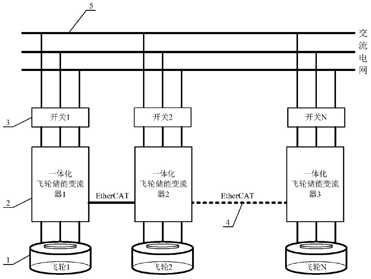
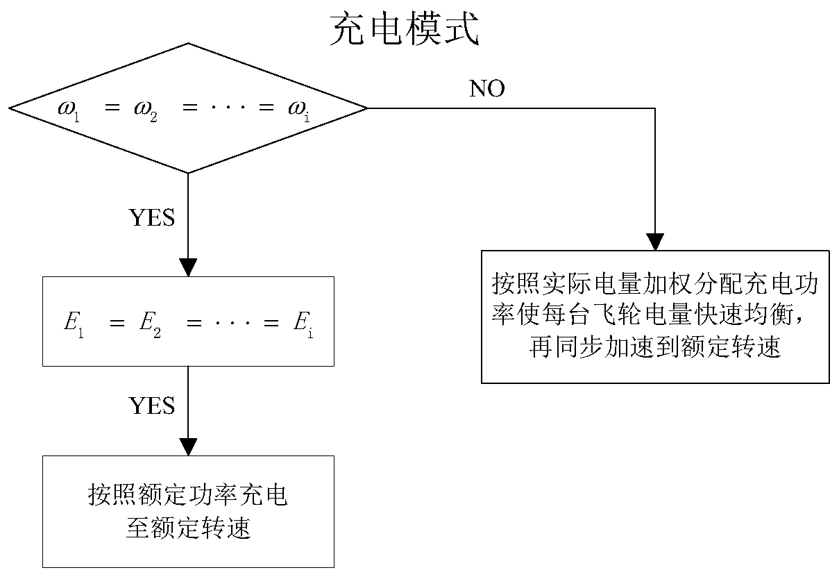
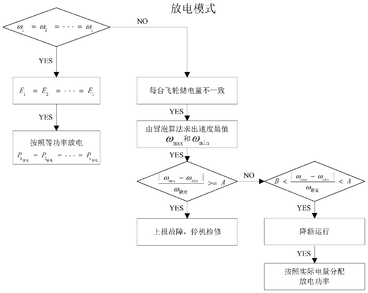
[0026] Such as figure 1 As shown, the array system of the present invention with large-scale and high-power energy storage flywheels in parallel includes an energy storage flywheel 1 , an integrated flywheel energy storage converter 2 , a grid-connected switch 3 , an EtherCAT bus 4 and a common AC bus 5 . The energy storage flywheel 1 is connected to the public AC bus 5 through the integrated flywheel energy storage converter 2 and the grid-connect...


PUM


Abstract

The invention relates to a control method of an energy storage flywheel parallel array system. A plurality of large-electric-quantity high-power energy storage flywheels are connected in parallel to form a flywheel array; in three different stages of charging, standby and discharging, electric quantity information fed back by each flywheel is detected, and different control algorithms are adoptedto reasonably distribute charging / discharging power to each flywheel, so that the electric quantity of each flywheel in the array tends to be consistent, and the optimal state of dynamic performance of each flywheel is achieved. The system comprises an energy storage flywheel, an integrated flywheel energy storage converter, a grid-connected switch and an EtherCAT bus. The integrated flywheel energy storage converter is based on a ZYNQ platform, the three-control integrated design of single flywheel charging and discharging control, magnetic suspension bearing control and a main control systemis achieved, the complex communication design between flywheel control systems is simplified, the hardware cost is reduced, and meanwhile the reliability of the system is improved.

Description

technical field [0001] The invention belongs to the field of electric power and relates to an array control method for parallel connection of high-power and high-power energy storage flywheels. Background technique [0002] Traditional energy storage frequency modulation can no longer meet the system requirements of high-power and high-frequency charging and discharging in the field of power system frequency modulation. Remarkable features such as low requirements are gradually welcomed and recognized by power system frequency modulation, rail transit, special equipment and other fields. [0003] In order to meet the needs of users in terms of electricity storage and power, most of the applications of energy storage flywheel systems in the industrial field are embodied in the form of multiple flywheels connected in parallel to form a flywheel array. Each energy storage flywheel is a high-inertia high-speed rotating energy storage body, and the amount of stored energy is rep...

Claims


Application Information

Patent Timeline
Patent Type & Authority Applications(China)
IPC IPC(8): H02J3/30H02J3/38
CPCH02J3/30H02J3/38Y02E60/16
Inventor 安俊佶王志强
Owner HUACHI KINETIC ENERGY (BEIJING) TECH CO LTD
Why Eureka
Try Eureka