Motor

A technology of motors and winding sleeves, which is applied in the field of motors, can solve problems affecting the operation of motors, and achieve the effect of reducing manufacturing costs

Inactive Publication Date: 2020-07-17
SUNONWEALTH ELECTRIC MACHINE IND
View PDF9 Cites 0 Cited by
  • Summary
  • Abstract
  • Description
  • Claims
  • Application Information

AI Technical Summary

Problems solved by technology

[0003] However, in the above-mentioned existing motor, when the electromagnetic field generated by the stator energization is too large, the permanent magnet is easily attracted by the stator, so that the permanent magnet mo

Method used


Image

  • Motor
  • Motor
  • Motor

Examples


no. 1 example

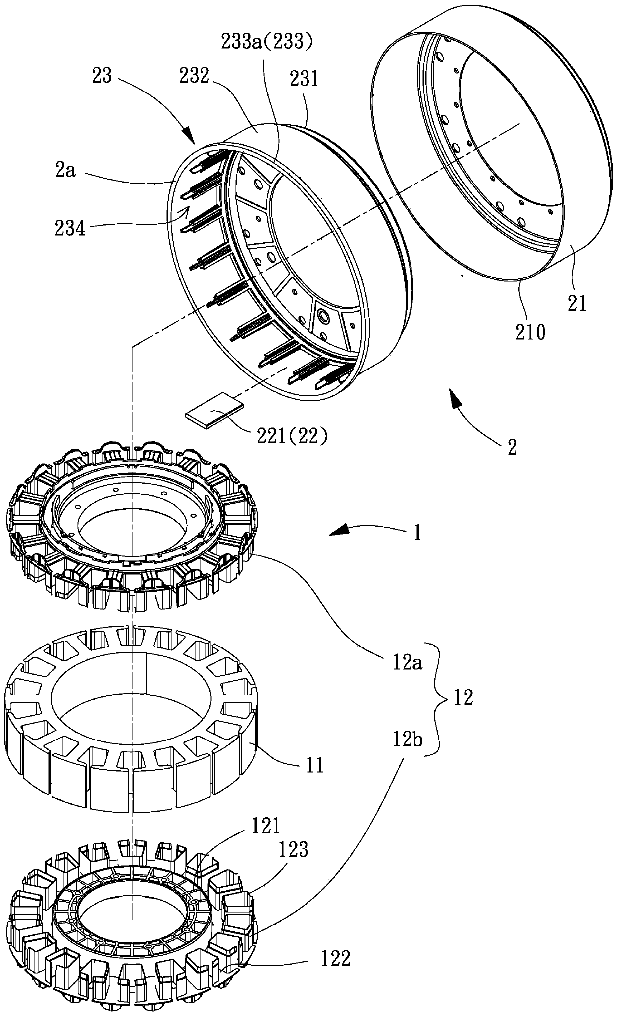
[0059] Please refer to figure 1 As shown, it is the first embodiment of the motor of the present invention, which includes a stator 1 and a rotor 2, and the ring of the rotor 2 is set on the outer periphery of the stator 1.

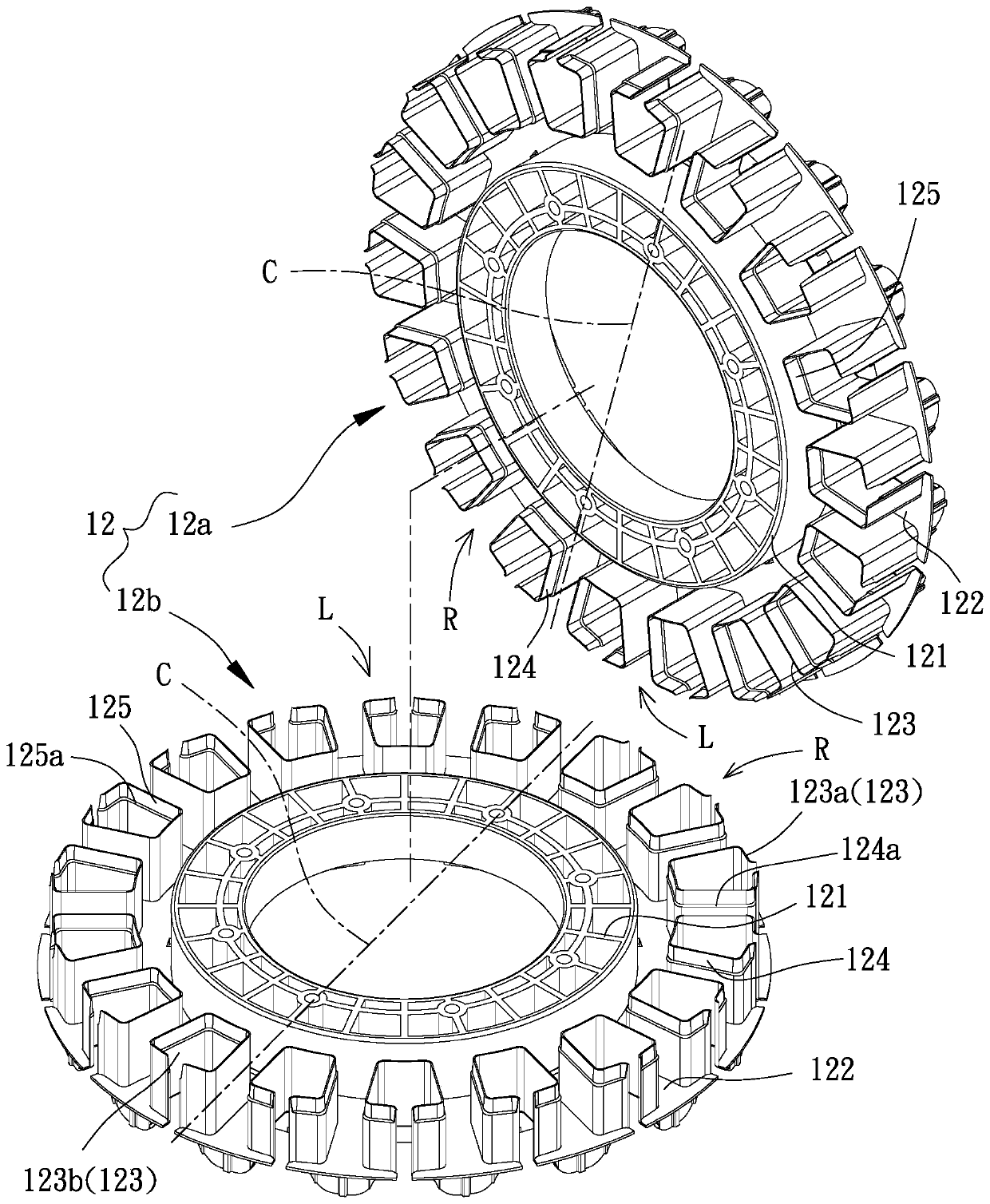
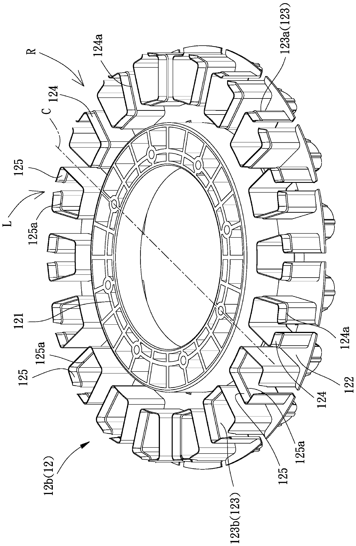
[0060] The stator 1 has an iron core 11 and a winding sleeve 12, and the iron core 11 can be axially stacked by a plurality of silicon steel sheets to a predetermined thickness. In addition, the winding set 12 can be formed by wrapping the iron core 11 in one piece, or can be combined with the iron core 11 by upper and lower winding sets respectively; in this embodiment, the winding set 12 can be There is an upper winding sleeve 12a and a lower winding sleeve 12b, the upper winding sleeve 12a and the lower winding sleeve 12b can be made of plastic material, and the lower end of the upper winding sleeve 12a and the lower winding sleeve The upper ends of the sleeves 12b are preferably overlapped to cover the iron core 11 together, so as to ensure that ther...


PUM


Abstract

A motor is used for settling problems of low insulating base structure strength and easy deformation of a motor rotor. The motor comprises the components of a stator; and a rotor which is annularly arranged at the periphery of the stator, wherein the rotor comprises a housing and a magnetic unit, wherein the magnetic unit is arranged at inside of the housing, one insulating base is arranged between the magnetic unit and the housing. The housing has an annular wall. The end edge of the insulating base has a snapping part which is snapped with the annular wall.

Description

technical field [0001] The invention relates to a motor, in particular to a motor capable of preventing deformation of an insulating seat. Background technique [0002] The existing motor mainly includes a stator and a rotor, and the rotor is rotatably combined with the outer periphery of a shaft of the stator. An iron core of the stator is wound with a coil, and a permanent magnet of the rotor is located inside a motor casing, so that an air gap can be formed between the permanent magnet and the iron core; and the motor also includes a An insulating ring between permanent magnets. Thereby, when the stator is energized, the insulating ring can prevent the current from being conducted to the motor casing through the permanent magnet and cause a leakage current phenomenon. An embodiment similar to the conventional motor has been disclosed in Taiwan Patent Publication No. M553518, Motor Insulation Structure. [0003] However, in the above-mentioned existing motor, when the e...

Claims


Application Information

Patent Timeline
IPC IPC(8): H02K5/04
CPCH02K5/04H02K5/08
Inventor 洪银树邱柏伟杨坤达
Owner SUNONWEALTH ELECTRIC MACHINE IND
Why Eureka
Try Eureka