Valve

A stator and protection sleeve technology, applied in the field of valves, can solve problems such as function damage, magnetic material corrosion, power loss, etc., and achieve the effect of simple manufacturing

Inactive Publication Date: 2020-07-17
CPT GRP GMBH
View PDF8 Cites 0 Cited by
  • Summary
  • Abstract
  • Description
  • Claims
  • Application Information

AI Technical Summary

Problems solved by technology

The disadvantage here is that the medium contains aggressive components which attack the magnetic material of the valve, so that the magnetic material is corroded
The result is power loss and impaired functionality

Method used


Image

  • Valve
  • Valve

Examples


Embodiment Construction

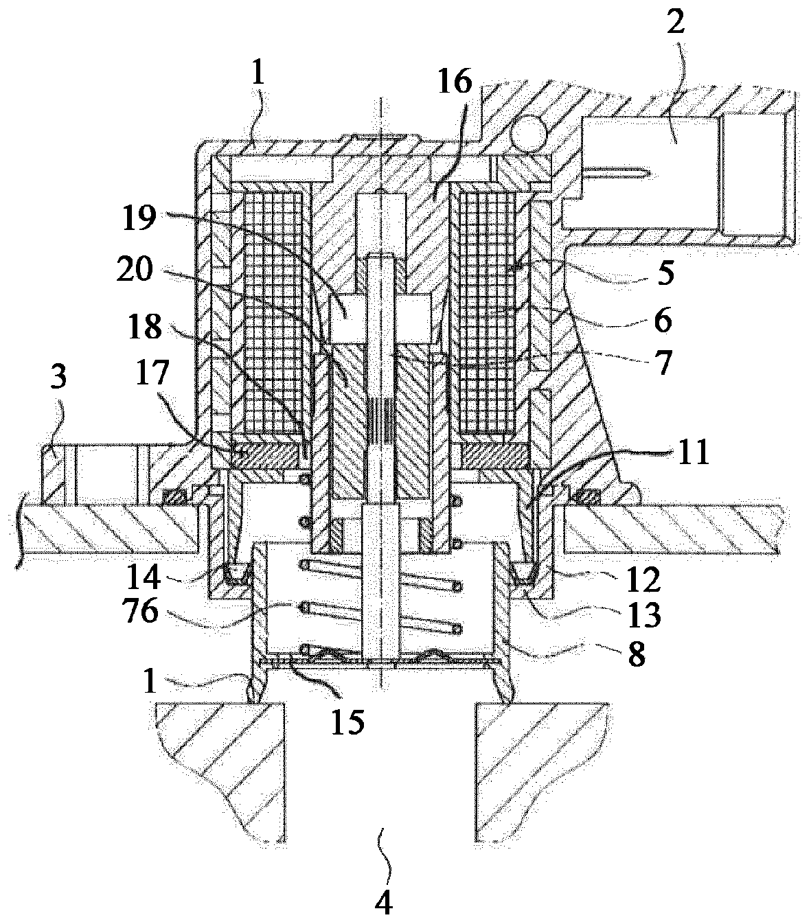
[0016] figure 1 The valve is shown, including the housing 1 . Furthermore, the housing 1 has an integrally formed flange 3 , via which the housing 1 is flanged to a turbocharger (not shown) in the region of the bypass line. The electrical contacting of the solenoid 5 , which is arranged in the housing 1 , takes place via the socket 2 . The solenoid 5 has a coil 6 which acts on a metal rod 7 . The metal rod 7 is connected to a pot-shaped piston 8 , which has a sealing surface 10 on the circumference of its base 9 , which cooperates with a valve seat (not shown). Here, the spring 7a pushes the piston 8 towards the valve seat. The housing 1 also has a cylindrical section 11 which extends in the direction of the piston 8 . A cylindrical bushing 12 connected to the housing surrounds the cylindrical section 11 . The cylindrical bush 12 has a radially inward flange 13 on which a seal 14 is placed. The seal 14 here seals the piston 8 relative to the housing 1 . The opening 15 i...


PUM


Abstract

The invention relates to a valve comprising a housing (1), a solenoid (5) arranged in the housing (1), a pin (7) that can be moved by the solenoid (5), a cup-shaped piston (8) which is connected to the pin (7), and a seal (14) arranged in the housing (1) for sealing the piston (8) against the housing (1). The seal (14) is a disk having a radially internal sealing surface (15), which is clamped atthe radially outer edge in the housing (12, 11).

Description

technical field [0001] The invention relates to a valve comprising a housing and a solenoid arranged in the housing, wherein the solenoid comprises a coil, an armature, an upper stator and a lower stator, the stators are designed such that when a magnetic force acts between the stators When the armature moves axially, the valve also includes a rod fixedly connected to the armature, a pot-shaped piston connected to the rod, and a spring to move the piston away from the solenoid when the magnetic force disappears. Background technique [0002] Such valves are used primarily as air steering valves on turbochargers in motor vehicles in order to open a bypass to the intake side during freewheeling and are therefore known. In order to prevent excessive braking of the turbocharger, but also to ensure a fast start-up, fast opening and closing of the valve is an important prerequisite. It is especially important when closing that an immediate closure is achieved by placing the pisto...

Claims


Application Information

Patent Timeline
Patent Type & Authority Applications(China)
IPC IPC(8): F16K27/02F02B37/18F16K31/06
CPCF16K27/029F16K31/0655F16K31/0675Y02T10/12F02B37/16H01F7/081H01F7/1607H01F2007/086
Inventor R·博南诺
Owner CPT GRP GMBH
Why Eureka
Try Eureka