Valve

A valve seat and piston technology, applied in the field of valves, can solve the problems of high manufacturing, complex, high cost, etc., and achieve the effect of easy installation and simple structure

Inactive Publication Date: 2020-07-17
纬湃技术有限公司
View PDF7 Cites 0 Cited by
  • Summary
  • Abstract
  • Description
  • Claims
  • Application Information

AI Technical Summary

Problems solved by technology

Disadvantageously, the piston and the V-shaped seal are relatively complex c

Method used


Image

  • Valve
  • Valve
  • Valve

Examples


Embodiment Construction

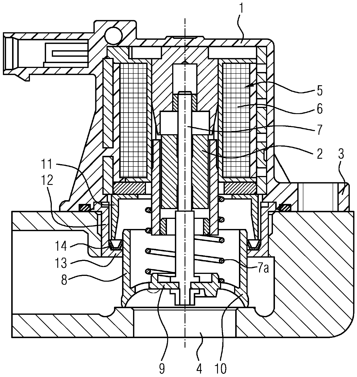
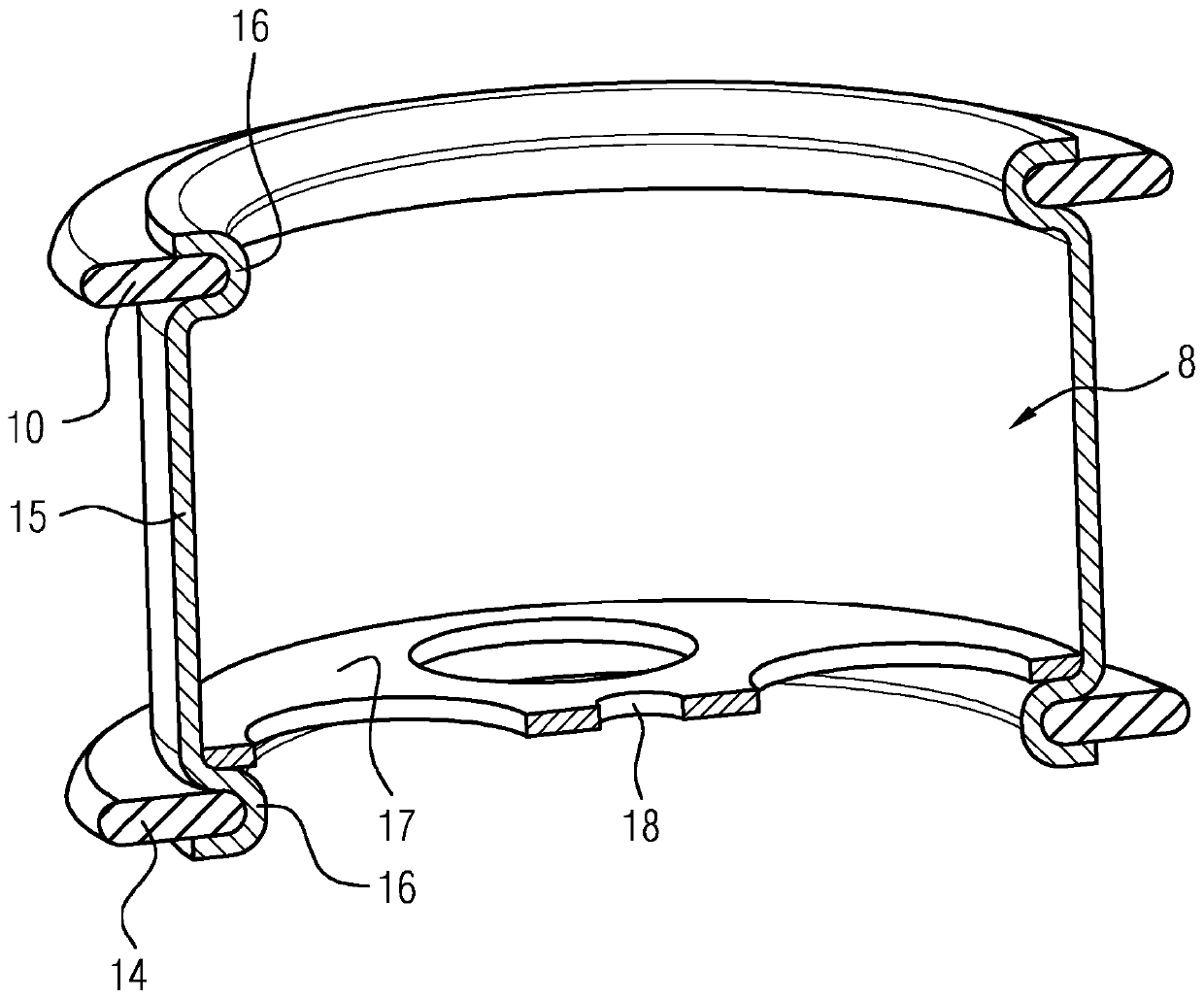
[0015] figure 1 The valve is shown, including the housing 1 . Furthermore, the housing 1 has an integral flange 3 , via which the housing 1 is flanged to a turbocharger (not shown) in the region of the bypass line 4 . A solenoid 5 with a coil 6 and a metal rod 7 is arranged in the housing 1 . The metal rod 7 is connected to a pot-shaped piston 8 which has a seal 10 on the circumference of its base 9 . In this case, the spring 7a pushes the piston 8 in the direction of the valve seat.

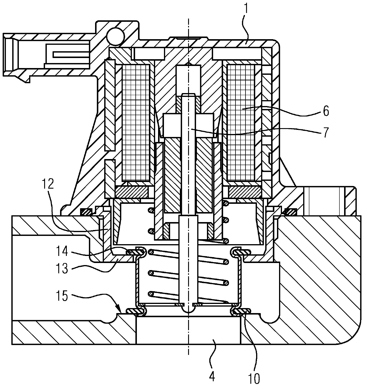
[0016] The housing 1 also has a cylindrical section 11 which extends in the direction of the piston 8 . A cylindrical bushing 12 connected to the housing surrounds the cylindrical section 11 . The cylindrical bush 12 has a radially inwardly facing flange 13 on which a V-shaped seal 14 is placed. The ends of the cylindrical section 11 hold the seal 14 in place. The inner wings of the seal 14 seal the piston 8 relative to the housing 1 . If the solenoid 5 is energized, a magnetic force acts...


PUM


Abstract

The invention relates to a valve comprising a housing, a solenoid arranged in the housing, a pin that can be moved by the solenoid and a cup-shaped piston that is connected to the pin, a seal that seals the piston with respect to the housing, and a seal that seals the piston with respect to a valve seat. The piston has on the side facing the housing and on the side facing the valve seat a respective radially peripheral receptacle, in each of which a seal is arranged.

Description

technical field [0001] The invention relates to a valve comprising: a housing; a solenoid arranged in the housing; a rod movable by the solenoid; a pot-shaped piston connected to the rod; a seal sealing the piston relative to the housing; and seals that seal the piston against the valve seat. Background technique [0002] Such valves are used primarily as air steering valves on turbochargers in motor vehicles in order to open a bypass to the intake side during freewheeling and are therefore known. In order to prevent excessive braking of the turbocharger, but also to ensure a fast start-up, fast opening and closing of the valve is an important prerequisite. It is especially important when closing that an immediate closure is achieved by placing the piston on the valve seat. The valve seat is formed by the housing of the turbocharger, to which the valve is flanged. In this case, the axially displaceable piston is sealed relative to the housing. Sealing is achieved by seal...

Claims


Application Information

Patent Timeline
IPC IPC(8): F16K39/02F02B37/18F16K1/46F16K31/06
CPCF16K1/46F16K31/0655Y02T10/12F02B37/16F16K27/029
Inventor S·O·格鲁尼斯R·博南诺
Owner 纬湃技术有限公司
Why Eureka
Try Eureka