
Cooled housing

A shell and cooling channel technology, applied in the field of electric motor shells, can solve the problem of high assembly costs and achieve the effect of ensuring a clear extension

Pending Publication Date: 2020-07-21
乔治费歇尔金属成型科技股份公司
View PDF10 Cites 0 Cited by
  • Summary
  • Abstract
  • Description
  • Claims
  • Application Information

AI Technical Summary

Problems solved by technology

[0006] In the case of the above-mentioned design of the electric motor housing, it is disadvanta

Method used


Image

  • Cooled housing
  • Cooled housing
  • Cooled housing

Examples


Embodiment Construction

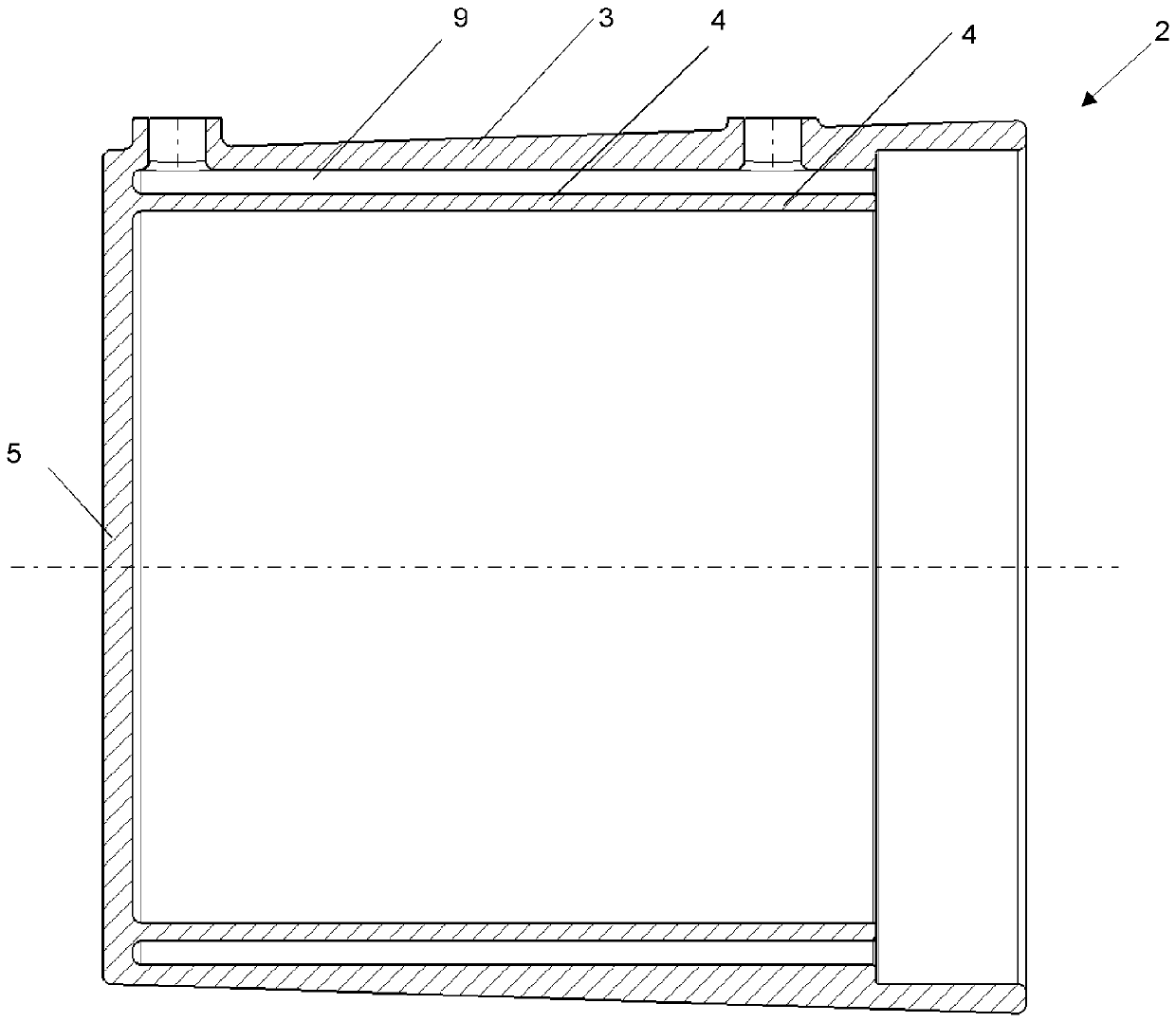
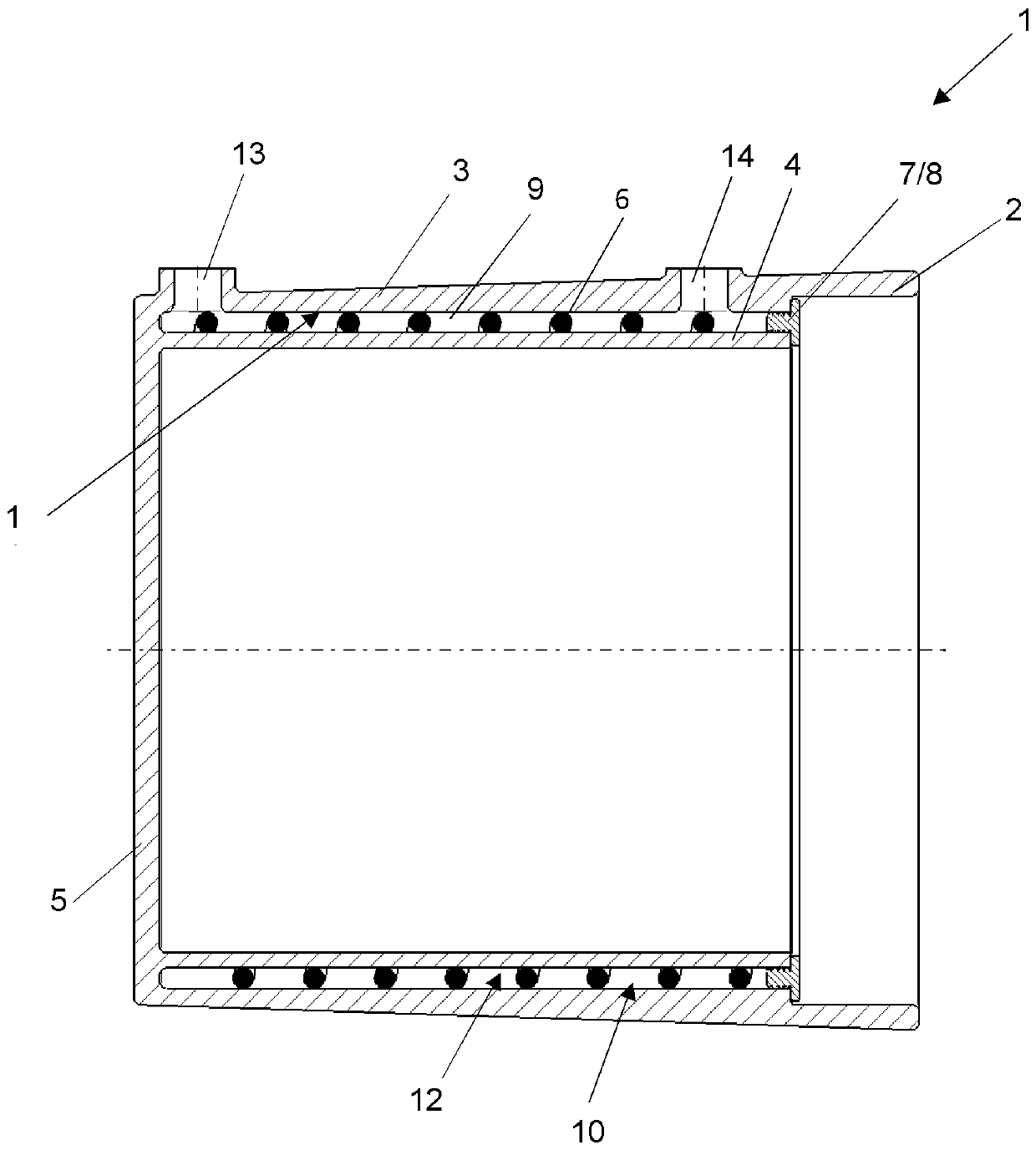
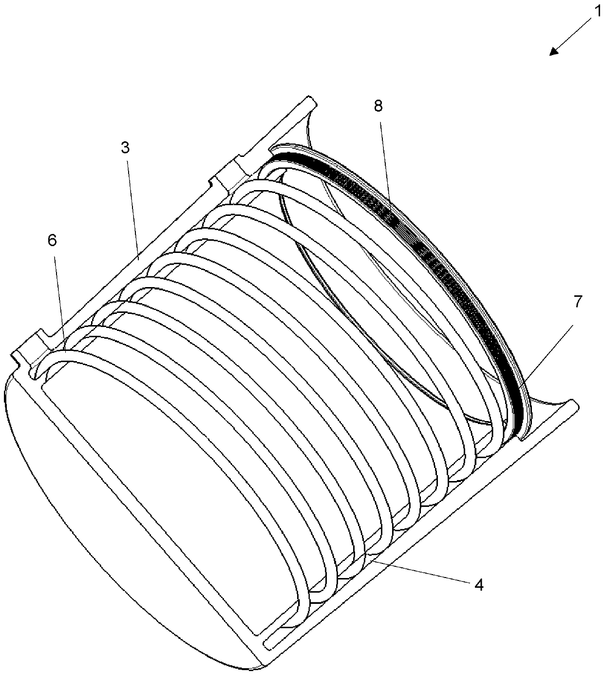
[0026] figure 1 The drawing represented in shows a longitudinal section through an electric motor housing 1 according to the invention. It is clearly evident that the housing 2 is formed in one piece, or in one piece, which in image 3 It is also evident in , where the housing 2 is shown separately. The housing 2 has an outer shell 3 , an inner shell 4 and a termination wall 5 . The outer shell 3 and the inner shell 4 are arranged concentrically to each other and have a circular cross section so as to thus resemble the housing 2 . The inner shell 4 is arranged spaced apart from the outer shell 3 such that a cooling gap 9 is formed between the interior 11 of the shell 3 and the exterior 12 of the inner shell. A helical element 6 is positioned in the cooling gap 9 , said helical element 6 forming a cooling channel 10 extending helically. The helical element 6 is tangential to the interior 11 of the outer shell 3 and the exterior 12 of the inner shell 4, thus forming a closed...


PUM


Abstract

An electric motor housing with cooling includes: a housing, the housing having a round cross-section, an outer shell, a terminating wall and an inner shell, the housing being formed as a one-piece lightweight metal cast component. A cooling gap is formed between the outer shell and the inner shell and a spiral-shaped element is arranged in the cooling gap. The spiral-shaped element includes a spiral-shaped cooling channel which runs between the windings of the spiral-shaped element.

Description

technical field [0001] The invention relates to an electric motor housing comprising a housing with cooling, preferably fluid cooling, wherein the housing has a circular cross-section, an outer shell, a terminating wall and an inner shell, wherein the housing is formed as a single piece of lightweight metal cast parts. Background technique [0002] Electric motors generate heat during their power output. Especially in the case of electric motors which output high power levels in motor vehicles, it is advantageous to cool said electric motors in order to ensure the efficiency of the electric motors. Overheating of electric motors can also lead to bearing damage, such as damage to the windings. [0003] Fluid-cooled housings for electric motors generally consist of at least two components. The fluid cooling housing generally has an inner cylindrical part, on the outside of which there are arranged helically running cooling channels which are incorporated into the outside, f...

Claims


Application Information

Patent Timeline
IPC IPC(8): H02K5/20
CPCH02K5/203H02K5/02H02K15/14H02K9/26H02K9/00H02K5/20
Inventor I.帕帕迪米特利欧
Owner 乔治费歇尔金属成型科技股份公司
Learn More