Interchange overpass

An overpass and intercommunication technology, which is applied in the field of interchange overpasses, can solve the problems of slow vehicle traffic and increase the overall area of ​​the bridge deck, and achieve the effects of slowing down the pressure of traffic flow, increasing the overall area, and optimizing the traffic mode

Pending Publication Date: 2020-07-24
李文彬
View PDF4 Cites 1 Cited by
  • Summary
  • Abstract
  • Description
  • Claims
  • Application Information

AI Technical Summary

Problems solved by technology

[0004] The present invention aims to provide an interchange overpass to solve the problem of slow vehicle traffic caused by all vehicles needing to enter the roundabout in the prior art, increase the overall area of ​​the bridge deck, and optimize various traffic modes

Method used


Image

  • Interchange overpass
  • Interchange overpass
  • Interchange overpass

Examples


Embodiment 1

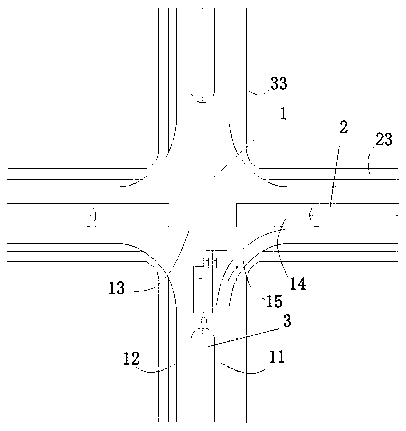
[0028] The interchange bridge is mainly composed of an upper-span traffic bridge 1, a level crossing road 2 and an underpassing road 3. According to the number of roads crossed, it is divided into three-limb interchange roads, four-limb interchange roads and multi-limb interchange roads. In this embodiment, it is mainly about the upper-span traffic bridge 1 of the interchange type overpass, which can be applied to three-limb overpass roads, four-limb overpass roads and multi-limb overpass roads. The present embodiment takes four-limb overpass roads as an example for illustration.

[0029] see figure 1 , shows the interchange structure of the present embodiment, wherein the overpass bridge 1 is a limb structure, and the structure of each limb is the same, specifically: including the up ramp 11 and the down ramp 12 in the same limb, the up ramp 11 and the down ramp A through lane on the level crossing road 2 is provided between the down ramps 12 , and a bridge deck awning area ...

Embodiment 2

[0049] Since the interchange bridge in Embodiment 1 has only a three-layer structure, only straight-going or turning lanes can be set under the bridge deck of the upper span, and the corresponding turning or going straight needs to be realized through the bridge deck. question.

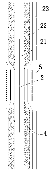
[0050] see Figure 6 The difference between this embodiment and Embodiment 1 is that the interchange bridge has changed from the original three-layer structure to a five-layer structure, and the underpass turn lane 205 located under the underpass through lane 201 and the underpass turn lane 205 located under the straight through lane have been newly added. 203 and the upper-span turning lane 202 between the upper-span bridge deck 204. Small vehicles can go straight and turn quickly through the dedicated lane, and can also be diverted through the bridge deck. Vehicles turn around and continue to pass through the dedicated lane in the bridge deck awning area, and large and medium-sized vehicles pass th...


PUM


Abstract

The invention relates to an interchange overpass. The overpass comprises an ascending ramp and a descending ramp which are located on the same limb, a straight traffic lane located on the flat-crossing road is arranged between the ascending ramp and the descending ramp, a bridge deck awning area communicated with at least two of the ascending ramp, the descending ramp and a bridge deck intersection is arranged between the ascending ramp and the descending ramp, a culvert is arranged between the bridge deck awning area and the straight traffic lane, and the straight traffic lane is provided with a concave road section located at the position of the culvert. The provided interchange overpass adopts a novel cross overpass scheme which arranges the deck awning area and horizontally-penetratingmotor vehicle lanes and adopts a double-concave design, and due to the downward concave design of the straight traffic lane, the feasibility of building a bridge deck awning exhibition area above theflat-crossing road surface becomes possible, and the overpass bridge deck, the motor vehicle ramps and the bridge deck awning exhibition area are connected together, so that a large overpass overallbridge deck is formed, and the requirements of right turning, left turning, straight moving, turning around, parking, waiting and the like of vehicles are met.

Description

technical field [0001] The invention belongs to the field of overpass engineering, in particular to an interchange type overpass. Background technique [0002] With the development of society, urban traffic problems are becoming more and more prominent, and problems such as traffic congestion, traffic accidents, and urban traffic pollution cannot be effectively solved. This urgently requires the acceleration of urban three-dimensional traffic construction, especially the three-dimensional transformation of urban crossroads. Construction, road width, ramp length, slope, remodelable intersection area, traffic mode, vehicle speed, etc. all affect the reconstruction design of the traffic bridge. However, existing technologies cannot effectively transform most intersections, and the three-dimensional transformation of two-way four-lane intersections is even more difficult. [0003] The existing technology usually has problems such as long designed ramps, high requirements for ro...

Claims


Application Information

Patent Timeline
IPC IPC(8): E01C1/04
CPCE01C1/04Y02A30/60
Inventor 李文彬
Owner 李文彬
Why Eureka
Try Eureka