
Steel beam and steel plate concrete combination shear wall connecting joint and construction method thereof

A combination of shear wall and steel plate concrete technology, which is applied in the direction of architecture and building structure, can solve the problems of exposed structure, occupying space, and affecting the appearance, so as to avoid brittle fracture and reduce stress concentration

Pending Publication Date: 2020-07-24
CENT SOUTH UNIV
View PDF0 Cites 0 Cited by
  • Summary
  • Abstract
  • Description
  • Claims
  • Application Information

AI Technical Summary

Problems solved by technology

However, the vertical stiffeners will occupy part of the usable space, causing the structure to be exposed and affecting the appearance

Method used


Image

  • Steel beam and steel plate concrete combination shear wall connecting joint and construction method thereof
  • Steel beam and steel plate concrete combination shear wall connecting joint and construction method thereof
  • Steel beam and steel plate concrete combination shear wall connecting joint and construction method thereof

Examples


Embodiment 1

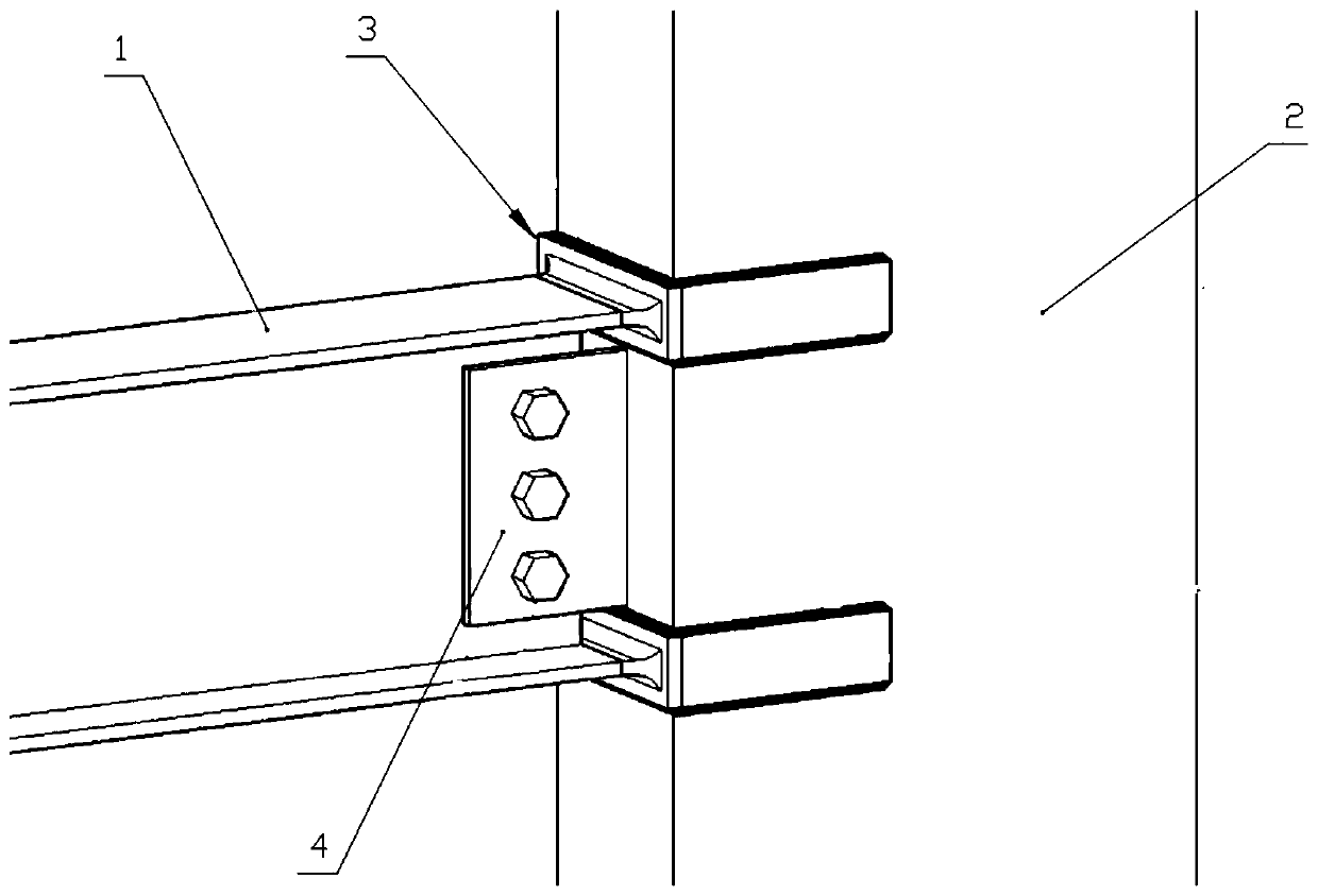
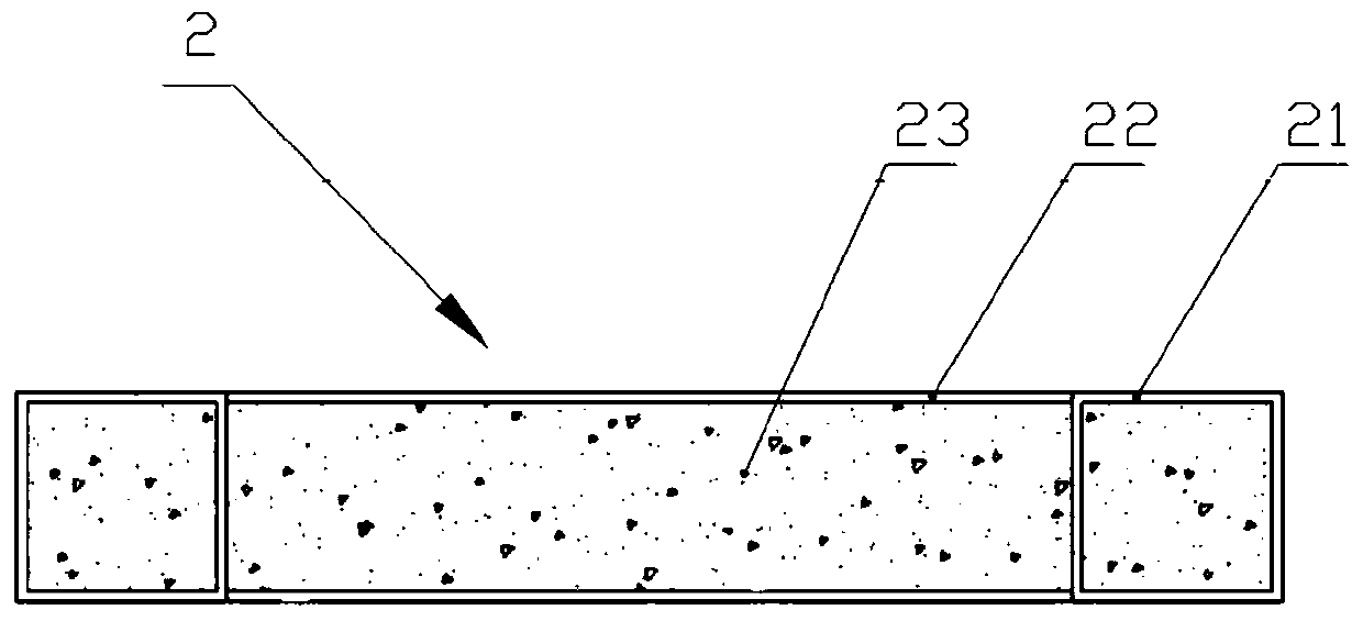
[0040] Preferred embodiment one, such as figure 1 As shown, the connection node disclosed in this embodiment is used for the assembly of the steel beam 1 and the steel plate concrete composite shear wall 2 . The connection node is composed of a pair of split steel connectors 3 and a shear plate 4 . Wherein the steel beam 1 is an I-shaped steel beam, and an installation hole is opened on its web. Such as figure 2 As shown, the steel plate concrete composite shear wall 2 includes an end column 21, an outer steel plate 22 and concrete 23, a pair of outer steel plates are connected between the two ends to form a filling cavity, and concrete is filled in the filling cavity and the inner cavity of the end column.

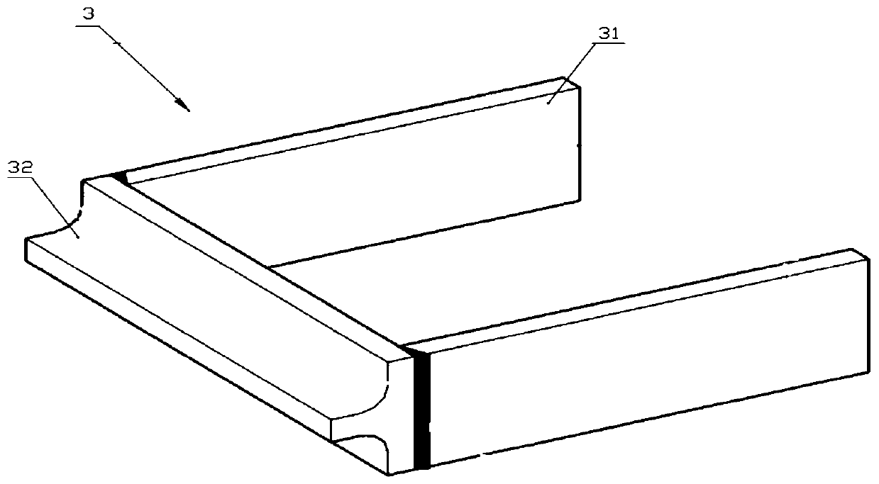
[0041] Such as image 3 As shown, the split steel connector 3 includes a T-shaped piece 31 and a side plate 32 . The width of the head of the T-shaped piece is slightly larger than the thickness of the shear wall 2, so that a pair of side panels are welded to the hea...

Embodiment 2

[0053] Preferred embodiment two, such as Figure 5 As shown, the connection node disclosed in this embodiment is used for detachable assembly of the steel beam 1 and the steel plate concrete composite shear wall 2 .

[0054] The difference between this embodiment and the preferred embodiment 1 is that the mounting holes are processed on the flange of the horizontal steel beam, the mounting holes are processed on the rod of the split steel connector, and the rod of the split steel connector is attached to the horizontal steel beam. The bolts passing through the connecting holes and the mounting holes are locked on the flanges with corresponding nuts.

[0055] In comparison, the benefits of the present invention are:

[0056] 1. When put into use, the split steel connector part is used as the connector between the horizontal steel beam and the end of the shear wall, and the transition area is a circular arc section, which can effectively reduce the force transmission between th...


PUM


Abstract

The invention discloses a steel beam and steel plate concrete combination shear wall connecting joint and a construction method thereof. The connecting joint comprises a horizontal steel beam, a steelplate concrete combination shear wall, subdivision profile steel connecting parts and a shear plate, the horizontal steel beam is I steel, the subdivision profile steel connecting parts are groove-shaped connecting parts formed through re-combining of T-shaped intersection sections subdivided from the profile steel and side flitch, one ends of the subdivision profile steel connecting parts are coated at the end of the shear wall, the other ends of the subdivision profile steel connecting parts are connected with a flange of the horizontal steel beam, the shear plate is mounted between the twosubdivision profile steel connecting parts, the inner end is connected with the shear wall, and the side face is connected with a web plate of the horizontal steel beam. The roots of the subdivisionprofile steel connecting parts are structural steel web plate and flange intersection positions and are rolled arc smooth transition, stress concentration during wall beam connection force transmission can be effectively reduced, meanwhile, the subdivision profile steel connecting parts have the large out-of-plane rigidity, out-of-plane deforming of a shear wall end plate can be effectively reduced, the joint is reasonable in stress, the structure is concise, and manufacturing and machining are convenient.

Description

technical field [0001] The invention belongs to the technical field of construction engineering, and in particular relates to a connection node of a steel beam and a steel plate concrete combined shear wall and a construction method thereof. Background technique [0002] Since the steel plate concrete composite shear wall can provide greater lateral stiffness, higher lateral bearing capacity and better energy dissipation capacity at a smaller wall thickness, it is currently the main structural system in steel structure houses. Types of. The end columns of steel plate concrete composite shear walls are often formed by steel tube concrete columns, or the entire wall is surrounded by steel plates, and the inner cavity is filled with concrete. Most of the horizontal beams in steel structure houses are H-shaped steel beams. When connecting them with steel plate concrete composite shear walls, the traditional method is to directly weld the H-shaped steel beams to the ends of the ...

Claims


Application Information

Patent Timeline
IPC IPC(8): E04B1/38E04B1/58
CPCE04B1/58E04B1/388
Inventor 余玉洁林思文曼孟轲赵凤涛
Owner CENT SOUTH UNIV
Features
  • Generate Ideas
  • Intellectual Property
  • Life Sciences
  • Materials
  • Tech Scout
  • Unparalleled Data Quality
  • Higher Quality Content
  • 60% Fewer Hallucinations
Learn More