Ventilation fan with protective mechanism

A protection mechanism and fan technology, applied in the direction of machines/engines, mechanical equipment, liquid fuel engines, etc., can solve the problems of damage to ventilation fans, lack of protective structures, etc.

Active Publication Date: 2020-07-24
绍兴上虞三禾风机有限公司
View PDF8 Cites 0 Cited by
  • Summary
  • Abstract
  • Description
  • Claims
  • Application Information

AI Technical Summary

Problems solved by technology

Existing ventilation fans need to connect the indoors with the outdoors, so as to discharge the indoor air to the outdoors, but the existing ventilation fans do not have a protective structure, so foreign stones and other impurities can easily enter the interior of the ventilation fan, which can easily cause damage to the ventilation fan

Method used


Image

  • Ventilation fan with protective mechanism
  • Ventilation fan with protective mechanism
  • Ventilation fan with protective mechanism

Examples


Embodiment 1

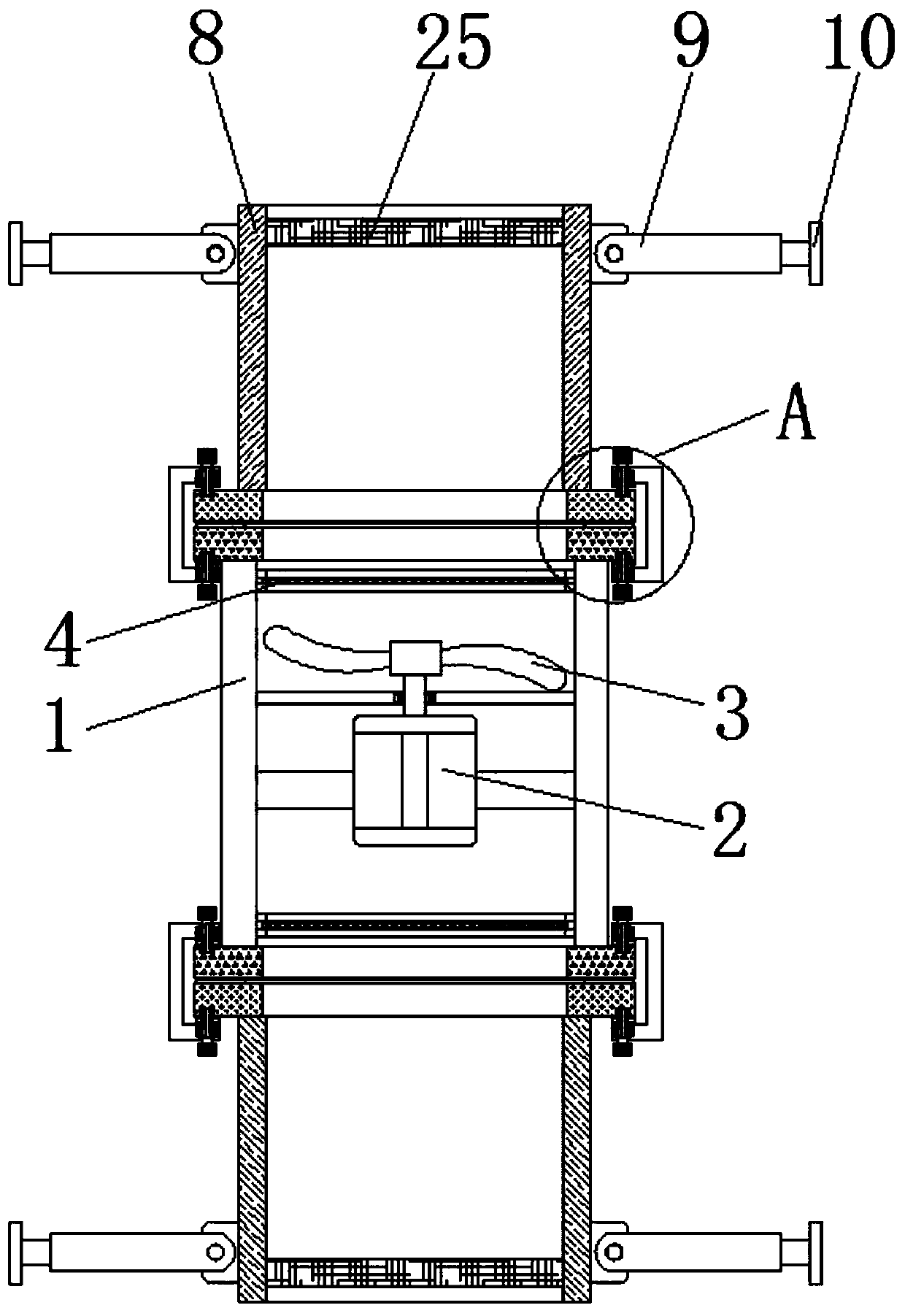
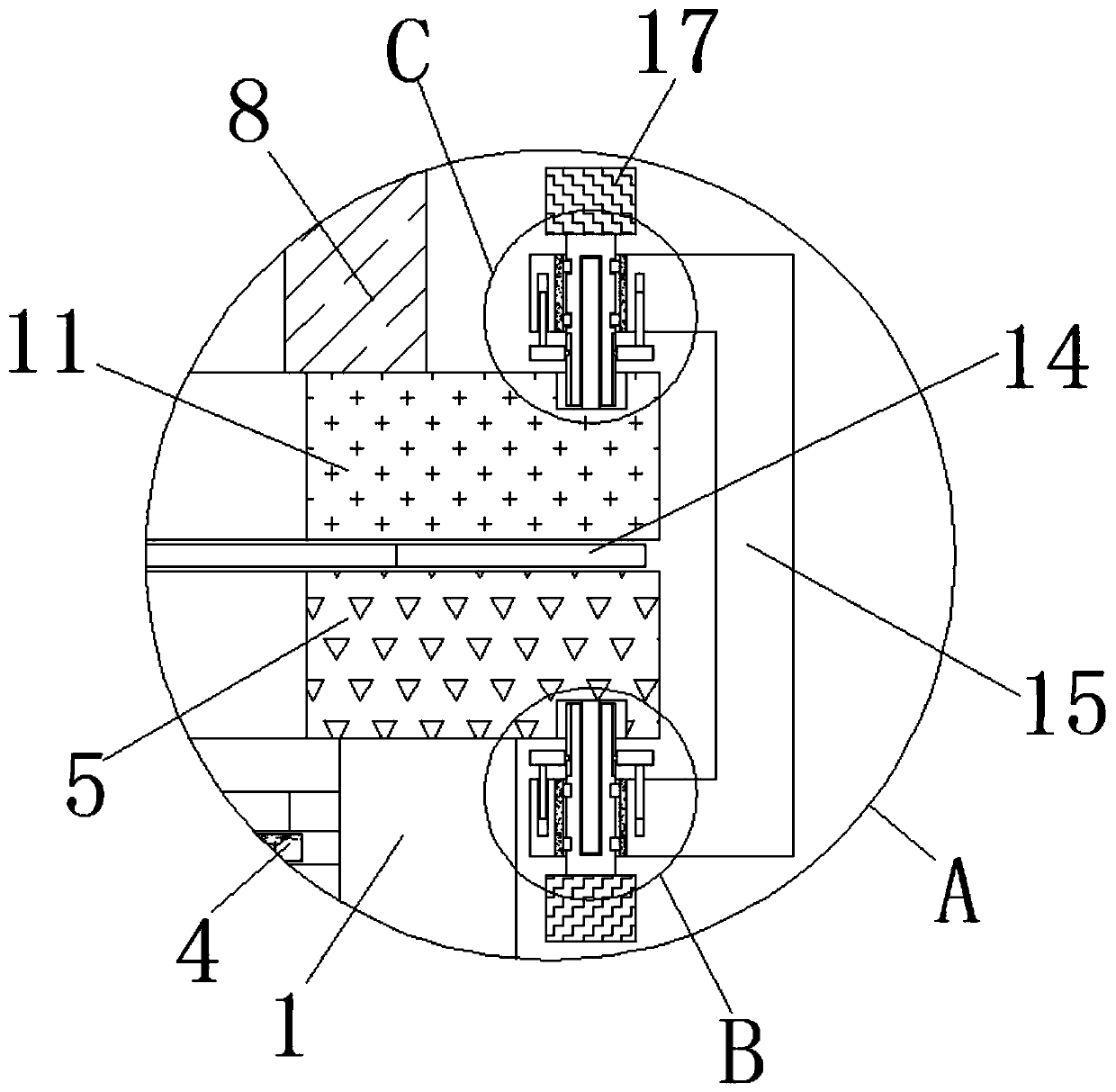
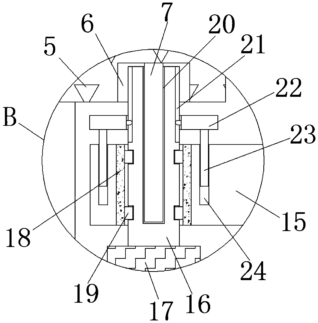
[0024] Such as Figure 1-4 As shown, a ventilation fan with a protective mechanism includes a fan installation cylinder 1, a drive device 2 is fixedly installed in the middle of the inner cavity of the fan installation cylinder 1, a blade assembly 3 is fixedly installed in the middle of the top of the drive device 2, and the fan installation cylinder 1 The top and bottom of the inner cavity are symmetrically fixed with dust-proof nets 4, and the top and bottom ends of the fan installation cylinder 1 are symmetrically fixedly connected with connecting rings 5, and the left and right sides of the opposite side of the two connecting rings 5 ​​are symmetrically provided with the second One rotating groove 6, the center of the inner wall of the bottom of the first rotating groove 6 is fixedly connected with the first guide column 7, the top and bottom of the fan installation cylinder 1 are symmetrically provided with a protective cylinder 8, and the left and right sides of the prote...

Embodiment 2

[0027] On the basis of Embodiment 1, the inner cavity of the fan installation cylinder 1 communicates with the outside world through the middle of its top and bottom, the inner cavity of the connecting ring 5 communicates with the outside world through the middle of its top and bottom, and the inner cavity of the protective tube 8 The cavity communicates with the outside world by the center of its top and bottom, and the inner chamber of the mounting ring 11 communicates with the outside world by the center of its top and bottom. The top and bottom of the gasket 14 fit the connecting ring 5 and the mounting ring 11 respectively.

Embodiment 3

[0029] On the basis of Embodiments 1 and 2, the protective tube 8 is rotatably connected with telescopic rods 9 through damping hinges, and the number of telescopic rods 9 is not less than two.


PUM


Abstract

The invention discloses a ventilation fan with a protective mechanism. The ventilation fan comprises a fan installing barrel, a driving device is fixedly installed in the middle of an inner cavity ofthe fan installing barrel, and a blade assembly is fixedly installed in the middle of the top of the driving device; the top and the bottom of the inner cavity of the fan installing barrel are symmetrically and fixedly provided with dust screens, and the two ends of the top and the bottom of the fan installing barrel are symmetrically and fixedly connected with connection rings; the left sides andthe right sides of the side surfaces, away from each other, of the two connection rings are symmetrically provided with first rotation grooves, and first guide columns are fixedly connected to the middles of the inner walls of the bottoms of the first rotation grooves; and the top and the bottom of the fan installing barrel are symmetrically provided with protective barrels. According to the ventilation fan with the protective mechanism, through cooperative operation of the protective barrels and sand prevention nets, sand is intercepted, and protection is provided for the blade assembly; andthrough moving of pressing rings on connection columns, clamping and fixing of U-shaped fixing clamping plates to connection rings and installing rings are completed, and a firm foundation is provided for connection between the fan installing barrel and the protective barrels.

Description

technical field [0001] The invention relates to the technical field of ventilation fans, in particular to a ventilation fan with a protection mechanism. Background technique [0002] Ventilation fan is a machine that relies on input mechanical energy to increase gas pressure and discharge gas. It is a driven fluid machine and is widely used in factories, mines, tunnels, ships and buildings for ventilation and dust removal, boilers and industrial furnaces. Ventilation and induction of air, cooling and ventilation in air conditioning equipment and household appliances, etc. Existing ventilation fans need to connect the indoors with the outdoors, so as to discharge the indoor air to the outdoors, but the existing ventilation fans do not have a protective structure, so foreign stones and other impurities can easily enter the interior of the ventilation fan, which can easily cause damage to the ventilation fan . Contents of the invention [0003] The main purpose of the prese...

Claims


Application Information

Patent Timeline
IPC IPC(8): F04D25/08F04D19/00F04D29/70F04D29/64F04D29/52F04D29/66F04D29/08
CPCF04D19/002F04D25/08F04D29/083F04D29/522F04D29/646F04D29/668F04D29/703
Inventor 章建浩
Owner 绍兴上虞三禾风机有限公司
Why Eureka
Try Eureka