
Flat tube and heat exchanger

A flat tube and channel technology, applied in the field of heat exchange devices, can solve the problems of difficult bending and low space utilization of A-shaped microchannel heat exchangers, and achieve the effect of compact structure, high space utilization and easy torsion

Pending Publication Date: 2020-07-24
ZHEJIANG DUNAN THERMAL SCI & TECH
View PDF0 Cites 0 Cited by
  • Summary
  • Abstract
  • Description
  • Claims
  • Application Information

AI Technical Summary

Problems solved by technology

[0005] The main purpose of the present invention is to provide a flat tube and heat exchanger to solve the problems of difficult bending and low space utilization of the A-shaped microchannel heat exchanger in the prior art

Method used


Image

  • Flat tube and heat exchanger
  • Flat tube and heat exchanger
  • Flat tube and heat exchanger

Examples


Embodiment Construction

[0041] It should be noted that, in the case of no conflict, the embodiments in the present application and the features in the embodiments can be combined with each other. The present invention will be described in detail below with reference to the accompanying drawings and examples.

[0042] It should be noted that the terminology used here is only for describing specific implementations, and is not intended to limit the exemplary implementations according to the present application. As used herein, unless the context clearly dictates otherwise, the singular is intended to include the plural, and it should also be understood that when the terms "comprising" and / or "comprising" are used in this specification, they mean There are features, steps, operations, means, components and / or combinations thereof.

[0043] For the convenience of description, spatially relative terms may be used here, such as "on ...", "over ...", "on the surface of ...", "above", etc., to describe the ...


PUM


Abstract

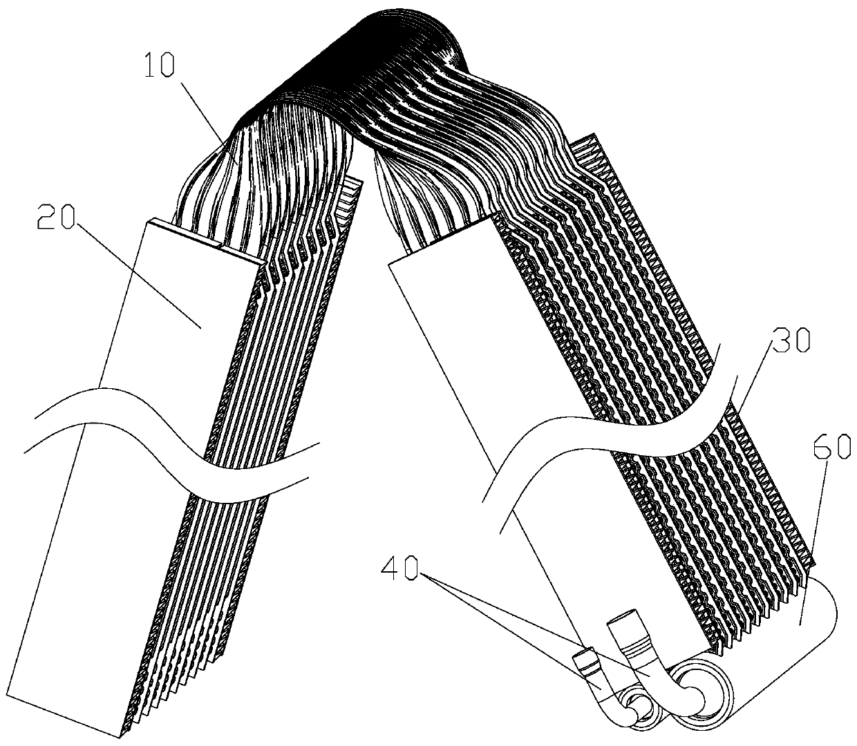
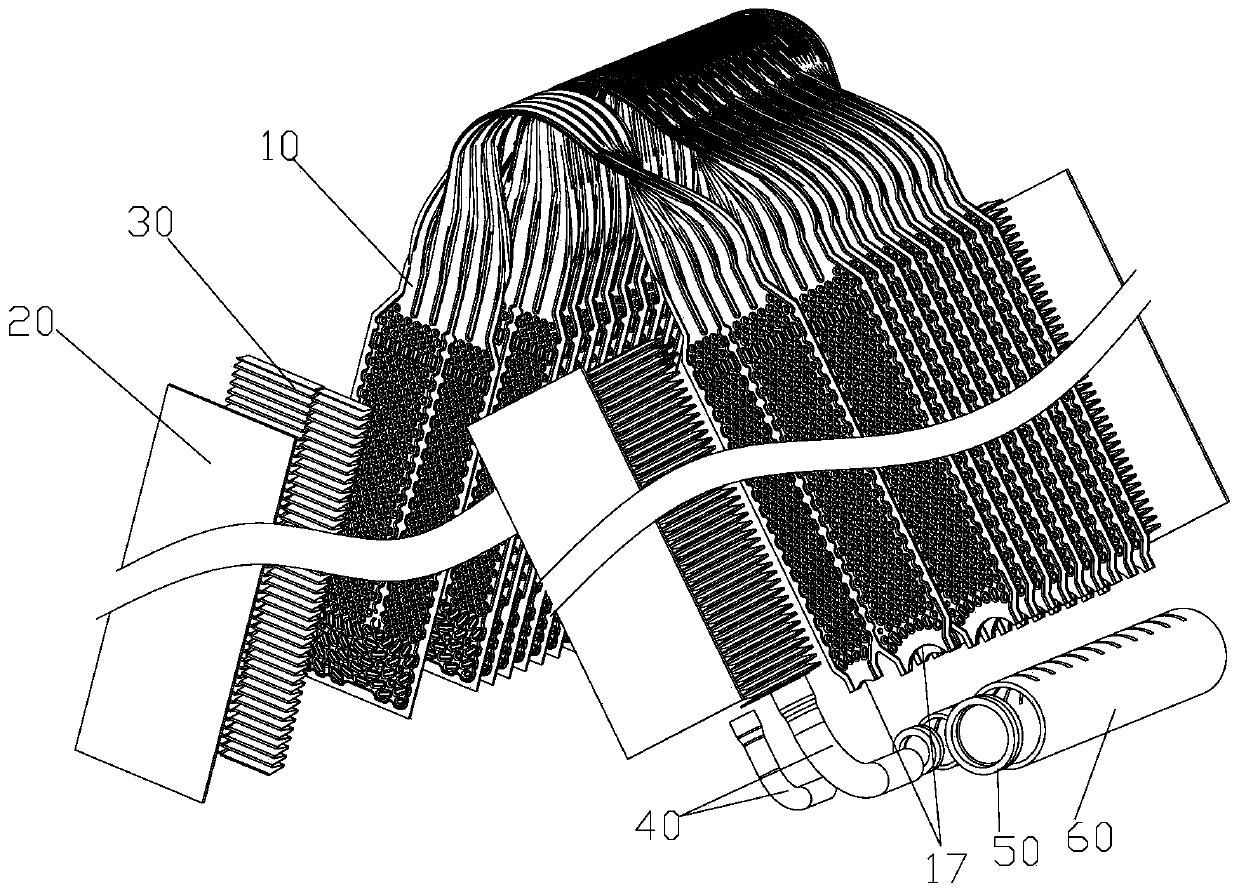
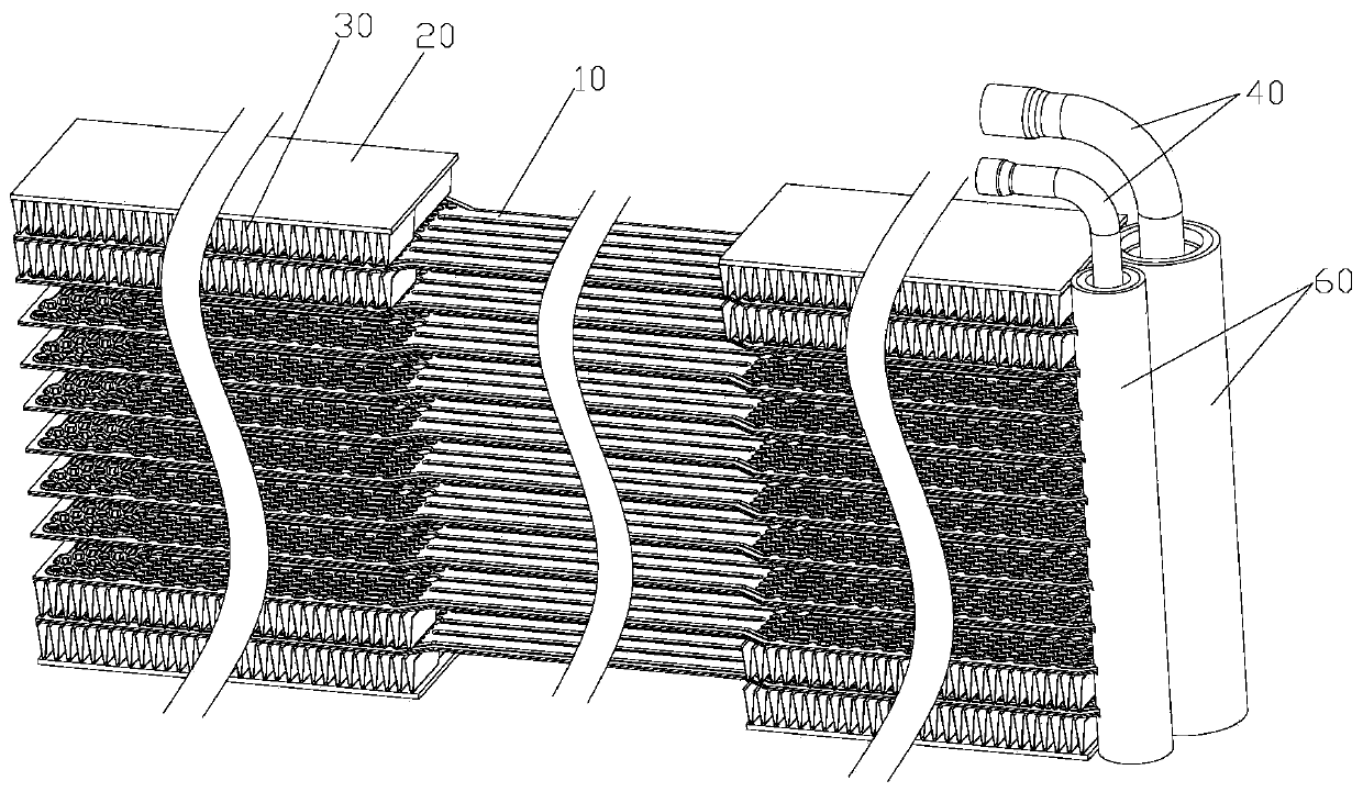
The invention provides a flat tube and a heat exchanger. The flat tube comprises a body; a separation part is arranged in the width direction of the body; the separation part is used for separating the body into a first channel and a second channel; a first end of the first channel communicates with a first end of the second channel; the body comprises at least two straight sections; every two adjacent straight sections are connected through a twisting section; and the width of the twisting sections is not larger than that of the straight sections. When the flat tube is actually bent, only one-time bending is needed at the twisting sections, only one row of core bodies is generated after twisting, the phenomenon that gaps exist between a front row of core bodies and a rear row of core bodies does not occur, the structure is compact, the space utilization rate is high, and the bending operation is convenient.

Description

technical field [0001] The invention relates to the technical field of heat exchange devices, in particular to a flat tube and a heat exchanger. Background technique [0002] The existing flat tube is formed by punching and tailor-welding two pieces of composite aluminum plates, punching out certain regular middle protrusions and edge protrusions, the two formed plates are attached to each other, and the corresponding protrusions are welded after brazing, The middle part forms a closed flow channel (except for the inlet and outlet), the middle protrusion plays the role of mechanical strengthening and heat transfer enhancement, and the side protrusion plays a sealing role after welding. [0003] The existing micro-channel "A" type heat exchanger has the advantages of drainage, compactness, and high efficiency, and is widely used in air conditioners such as household appliances and ducted appliances, and has a huge market potential. [0004] The double-row "A" type microchann...

Claims


Application Information

Patent Timeline
Patent Type & Authority Applications(China)
IPC IPC(8): F28D1/047F28F1/02F28F9/18F28F21/08
CPCF28D1/0471F28F1/02F28F9/18F28F21/08
Inventor 魏文建梁新宇马文勇
Owner ZHEJIANG DUNAN THERMAL SCI & TECH
Learn More