
Detection method, device and equipment for halogen lamp

A detection method and technology for halogen lamps, which are used in lamp testing, testing optical performance, geometric characteristics/aberration measurement, etc., can solve problems such as failure to warn of halogen lamp damage, and achieve the effect of reducing abnormal maintenance frequency and improving competitiveness.

Active Publication Date: 2020-07-24
BEIJING NAURA MICROELECTRONICS EQUIP CO LTD
View PDF11 Cites 0 Cited by
  • Summary
  • Abstract
  • Description
  • Claims
  • Application Information

AI Technical Summary

Problems solved by technology

[0005] The purpose of the embodiments of the present application is to provide a detection method, device and equipment for a halogen lamp, so as to solve the problem that the damage of the halogen lamp cannot be warned

Method used


Image

  • Detection method, device and equipment for halogen lamp
  • Detection method, device and equipment for halogen lamp
  • Detection method, device and equipment for halogen lamp

Examples


Embodiment Construction

[0027] The embodiments of the present application provide a detection method, device and equipment for a halogen lamp, so as to solve the problem that the damage of the halogen lamp cannot be early-warned.

[0028] In order to enable those skilled in the art to better understand the technical solutions in the present application, the technical solutions in the embodiments of the present application will be clearly and completely described below in conjunction with the drawings in the embodiments of the present application. Obviously, the described The embodiments are only some of the embodiments of the present application, but not all of them. Based on the embodiments in this application, all other embodiments obtained by persons of ordinary skill in the art without creative efforts shall fall within the scope of protection of this application.

[0029] figure 1 It is a schematic flowchart of a detection method for a halogen lamp according to an embodiment of the present inve...


PUM


Abstract

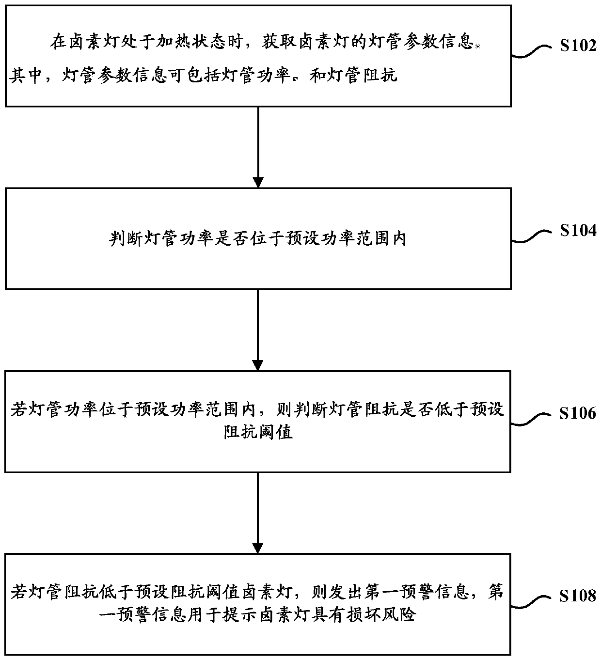
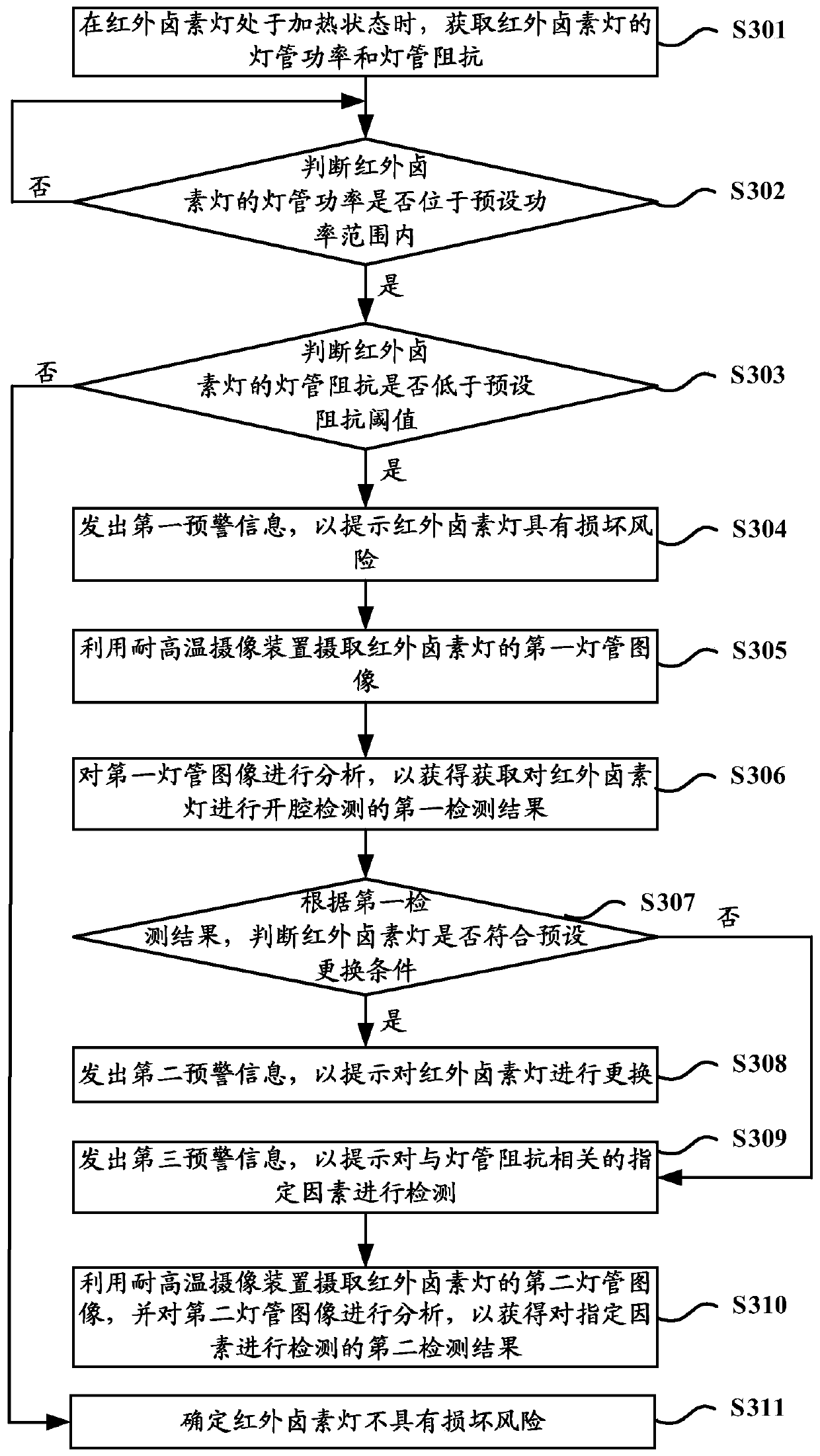
The embodiment of the invention discloses a detection method, device and equipment for a halogen lamp, and aims to solve the problem that early warning cannot be performed on the damage of the halogenlamp. The method comprises the following steps of: when the halogen lamp is in a heating state, acquiring lamp tube parameter information of the halogen lamp, wherein the lamp tube parameter information comprises lamp tube power and lamp tube impedance; judging whether the lamp tube power is within a preset power range or not; if the lamp tube power is within the preset power range, judging whether the lamp tube impedance is lower than a preset impedance threshold value or not; and if the lamp tube impedance is lower than the preset impedance threshold value, transmitting first early warninginformation, wherein the first early warning information is used for prompting that the halogen lamp has a damage risk. Through adoption of the technical scheme, an early warning effect on the halogenlamp with the damage risk is achieved, and the situation that the halogen lamp is damaged and then affects peripheral components of the equipment is avoided, so that the abnormal maintenance frequency of the equipment is lowered, and the competitiveness of the equipment is enhanced.

Description

technical field [0001] The invention relates to the technical field of microelectronics and equipment detection, in particular to a detection method, device and equipment for a halogen lamp. Background technique [0002] Chemical vapor deposition (Chemical Vapor Deposition, CVD) epitaxy, as a vapor phase epitaxial growth technology that deposits solid films on the surface of the substrate by means of space gas phase chemical reactions, has simple related equipment, easy control of growth parameters, and good repeatability , is currently the main method of silicon epitaxial growth. [0003] The current CVD silicon epitaxial equipment mainly has two types: multi-chip and single-chip. Multi-wafer CVD equipment uses induction heating, which has low heating and cooling efficiency; and vacuum manipulators are used to pick and place wafers, which is increasingly difficult to meet customer requirements for high wafer edge quality. In addition, the larger rectangular chamber design...

Claims


Application Information

Patent Timeline
Patent Type & Authority Applications(China)
IPC IPC(8): G01R31/44G01M11/02
CPCG01R31/44G01M11/02G01M11/025Y02B20/00
Inventor 陈路路
Owner BEIJING NAURA MICROELECTRONICS EQUIP CO LTD
Learn More