Stabilizing device for steel plate welding

A technology for stabilizing devices and steel plates, applied in auxiliary devices, welding equipment, auxiliary welding equipment, etc., can solve problems such as large welding errors of steel plates, deviation of steel plate positions, etc., and achieve rapid cooling, convenient handling, and simple operation.

Inactive Publication Date: 2020-07-28
易明端
View PDF0 Cites 5 Cited by
  • Summary
  • Abstract
  • Description
  • Claims
  • Application Information

AI Technical Summary

Problems solved by technology

[0004] The purpose of the present invention is to solve the problem that most of the existing steel plates do not have a good fixing device to fix the steel plates when welding, which leads to the situation that the position of the steel plates is prone to deviation during the welding process, resulting in large welding errors of the steel plates disadvantages, and proposed a stable device for steel plate welding

Method used


Image

  • Stabilizing device for steel plate welding
  • Stabilizing device for steel plate welding
  • Stabilizing device for steel plate welding

Examples


Embodiment 1

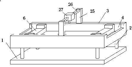
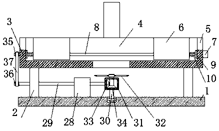
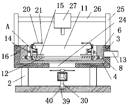
[0028] refer to Figure 1-5 , a stabilizing device for steel plate welding, comprising a base 1, four symmetrically arranged support legs 2 are fixedly installed on the top of the base 1, and the same operation platform 3 is fixedly installed on the top of the four support legs 2, and the operation platform 3 The top of the sliding groove 4 is provided with a sliding groove 4, and the inner wall of both sides of the sliding groove 4 is provided with a through groove 5. Two symmetrically arranged moving plates 6 are slidably connected in the sliding groove 4, and a motor 7 is fixedly installed on one side of the console 3. The inner wall of the slide groove 4 is rotationally connected with two symmetrically arranged two-way screws 8, and one of the two two-way screws 8 is fixedly connected with the output shaft of the motor 7, and the two two-way screws 8 are all connected to the two moving plates. 6 sliding connection, the top of the moving plate 6 is provided with a placement...

Embodiment 2

[0039] refer to Figure 1-5 , a stabilizing device for steel plate welding, comprising a base 1, four symmetrically arranged support legs 2 are welded on the top of the base 1, the same operating platform 3 is welded on the top of the four supporting legs 2, and the top of the operating platform 3 A sliding groove 4 is provided, and through grooves 5 are provided on the inner walls of both sides of the sliding groove 4. Two symmetrically arranged moving plates 6 are slidably connected in the sliding groove 4, and a motor 7 is welded on one side of the console 3. The sliding groove 4 Two symmetrically arranged two-way screws 8 are rotationally connected on the inner wall of the two-way screw rod 8, and one two-way screw rod 8 in the two two-way screw rods 8 is fixedly connected with the output shaft of the motor 7, and the two two-way screw rods 8 are all slidably connected with the two moving plates 6 , the top of the moving plate 6 is provided with a placement groove 11, the ...


PUM


Abstract

The invention belongs to the technical field of steel plate welding and fixing equipment, and particularly relates to a stabilizing device for steel plate welding. The stabilizing device aims at solving the problems that when most of existing steel plates are welded, no good fixing device is used for fixing the steel plates, the steel plates are prone to position deviation in the welding process,and the steel plate welding error is large. According to the scheme, the stabilizing device comprises a base, wherein four symmetrically-arranged supporting legs are fixedly installed on the top of the base; the same operation table is fixedly installed on the top ends of the four supporting legs; a sliding groove is formed in the top of the operation table; through grooves are formed in the innerwalls of the two sides of the sliding groove; and two symmetrically-arranged moving plates are connected into the sliding groove in a sliding mode. The stabilizing device is easy to operate and convenient to use, two steel plates needing to be welded can be rapidly clamped and fixed, the steel plates can be stably welded, meanwhile, the welded steel plates can be rapidly cooled, and taking is convenient.

Description

technical field [0001] The invention relates to the technical field of steel plate welding and fixing equipment, in particular to a stabilizing device for steel plate welding. Background technique [0002] The steel plate is a flat-shaped steel material that is poured with molten steel and pressed after cooling. In the process of processing the steel plate, it is often necessary to weld the two steel plates together. The two steel plates need to be pieced together and then welded along the gap. [0003] Most of the existing steel plate welding does not have a good fixing device to fix the steel plate, resulting in the position deviation of the steel plate during the welding process, resulting in a large welding error of the steel plate, so we propose a method for Stabilized device for steel plate welding. Contents of the invention [0004] The purpose of the present invention is to solve the problem that most of the existing steel plates do not have a good fixing device t...

Claims


Application Information

Patent Timeline
Patent Type & Authority Applications(China)
IPC IPC(8): B23K37/04B23K37/00B23K37/02B23K103/04B23K101/18
CPCB23K37/003B23K37/02B23K37/0408B23K2101/185B23K2103/04
Inventor 易明端
Owner 易明端
Why Eureka
Try Eureka