
Obstacle clearing device with detection mechanism for rail transit

A technology of detection mechanism and obstacle removal device, which is applied in the field of rail transit, can solve the problems of double-layer rubber plate damage, low service life, and huge impact energy of sundries, and achieve the effect of prolonging service life and preventing damage

Active Publication Date: 2020-07-28
邵丽丹
View PDF9 Cites 2 Cited by
  • Summary
  • Abstract
  • Description
  • Claims
  • Application Information

AI Technical Summary

Problems solved by technology

The obstacle clearing device in the above-mentioned patent has the following disadvantages: debris directly impacts on the double-layer rubber plate structure, and since the train is generally running faster, huge impact energy will be generated when the debris directly impacts, and the absence of a buffer device will cause double-layer rubber plate structure The layer rubber plate is damaged by impact, and the service life is low

Method used


Image

  • Obstacle clearing device with detection mechanism for rail transit
  • Obstacle clearing device with detection mechanism for rail transit
  • Obstacle clearing device with detection mechanism for rail transit

Examples


Embodiment 1

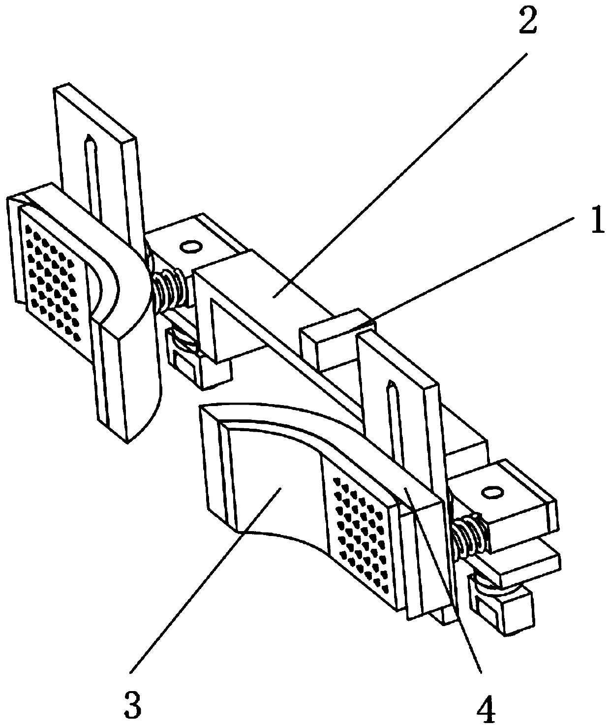
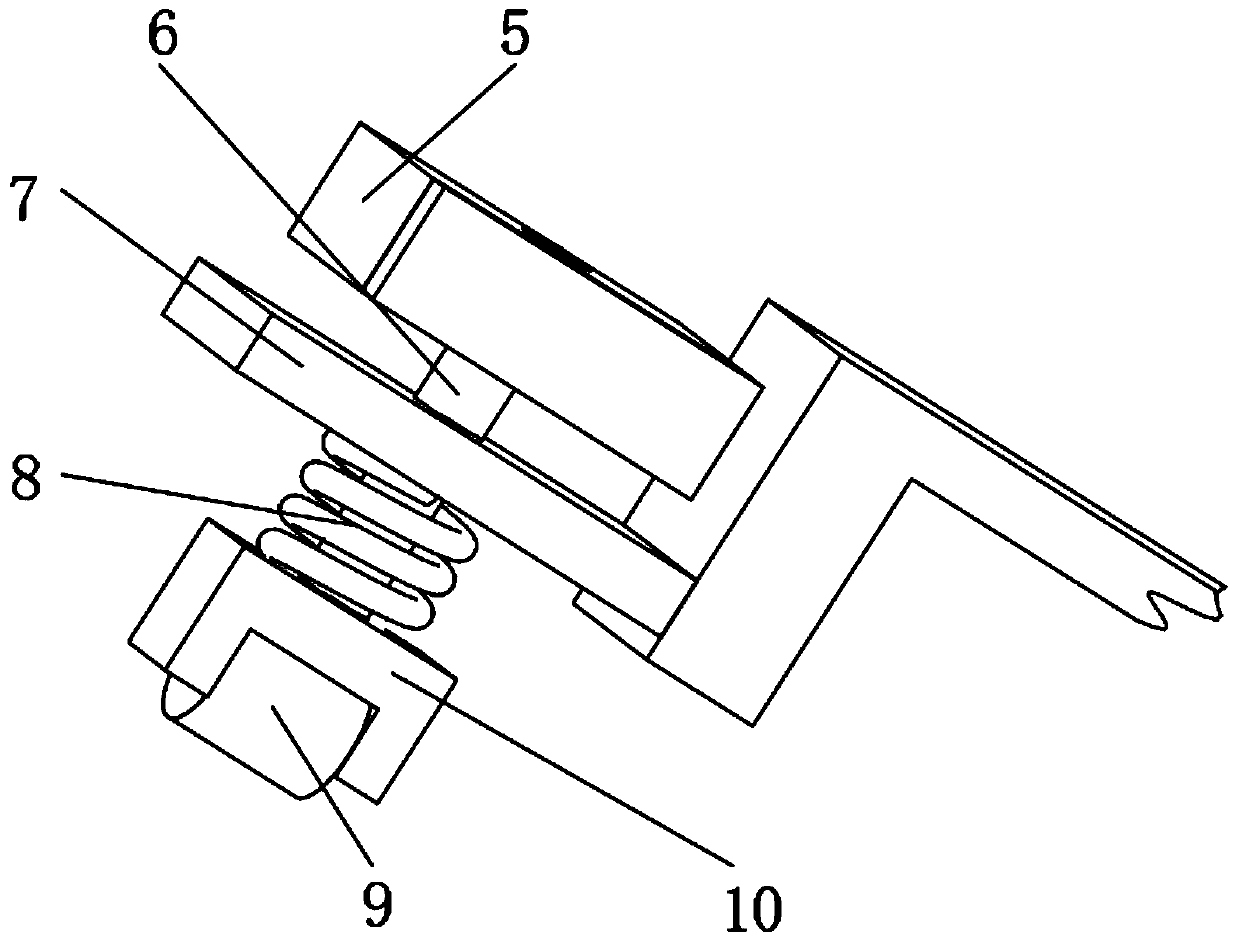
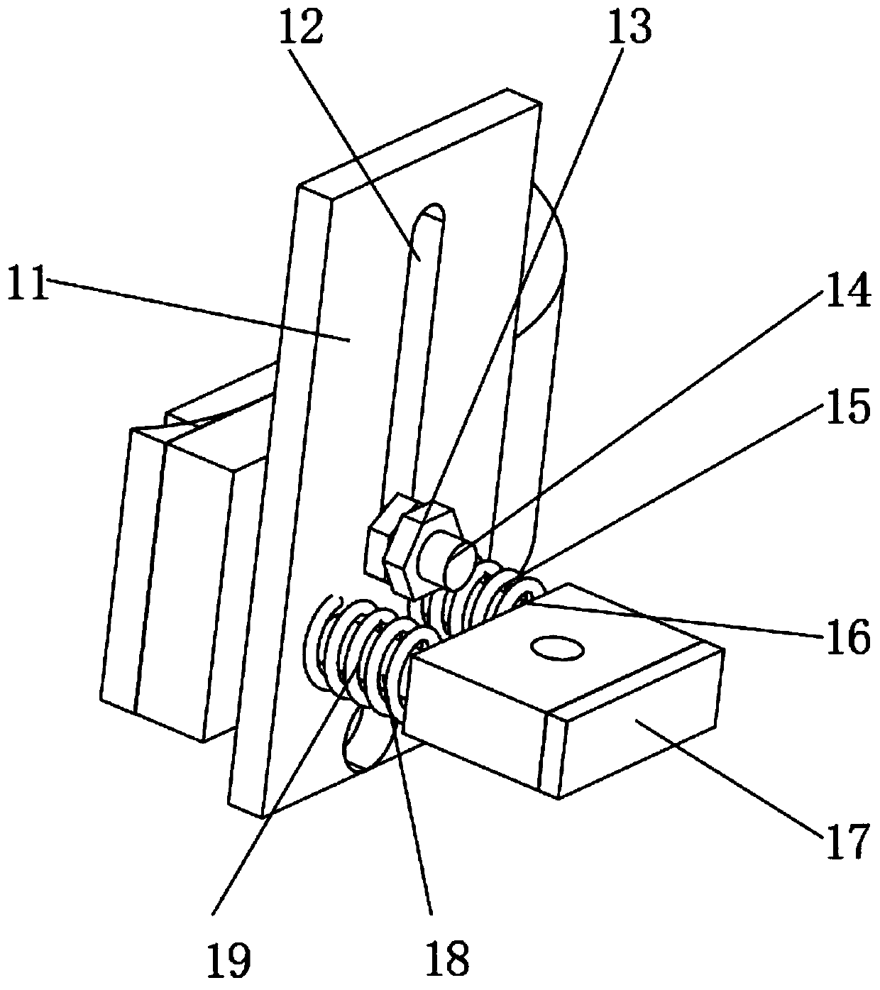
[0035] A kind of obstacle removal device with detection mechanism for rail transit, such as figure 2As shown, it includes the connecting steel plate 1 fixed on the bottom of the head car compartment and the electronic system placed in the cab, the outer wall of the bottom of the connecting steel plate 1 is fixed with the connecting beam 2 by bolts, and the outer wall of the connecting beam 2 is fixed with an anti-contact steel plate by bolts 7. The inner wall of the anti-contact steel plate 7 is provided with an anti-contact device, one side of the anti-contact device is provided with a clearing mechanism, and the opposite side of the clearing mechanism and the anti-contact device is provided with the same buffer mechanism; the connecting steel plate 1 is fixed in the direction of train travel At the bottom of the carriage at the front end, the connecting beam 2 is fixedly connected to the connecting steel plate 1 as the support of the whole device, and the device is arranged ...

Embodiment 2

[0041] A kind of obstacle removal device with detection mechanism for rail transit, such as Figure 4 , 6 As shown, in order to solve the problem that the electronic system can detect the number of times of obstacle removal and the pressure change of the impact rubber 3 during the obstacle removal process; this embodiment makes the following improvements on the basis of embodiment 1: the electronic system includes an electronic control system and Auxiliary structure, the electric control system includes piezoelectric ceramics 20 and a main board 29, the piezoelectric ceramics 20 is embedded on the inner wall of the impact rubber 3, the piezoelectric ceramics 20 is electrically connected with the main board 29, and the top outer wall of the main board 29 is respectively welded with signal conversion Module 31, central processing module 32, counting module 33 and control module 34, signal conversion module 31, central processing module 32, counting module 33 and control module 3...


PUM


Abstract

The invention discloses an obstacle clearing device with a detection mechanism for rail transit, relates to the technical field of rail transit, and aims to solve the problem that sundries on a rail influence driving safety. The device comprises a connecting steel plate fixed to the bottom of a carriage of a head vehicle, and an electronic system placed in a cab. A connecting beam is fixed to theouter wall of the bottom of the connecting steel plate through bolts, an anti-contact steel plate is fixed to the outer wall of the connecting beam through bolts, an anti-contact device is arranged onthe inner wall of the anti-contact steel plate, and an obstacle removing mechanism is arranged on one side of the anti-contact device. According to the invention, the obstacle clearing mechanism is arranged; when there are sundries on the rails, striking rubber can strike the sundries away from the rails, and the striking rubber, the fixed steel plate and the curved steel plate are all in curvedsurface design, so that when the sundries strike the striking rubber, the direction of reaction force generated by the striking rubber to the sundries deviates to the inner side, the sundries finallyfall between the two rails, and the safety of nearby personnel is guaranteed.

Description

technical field [0001] The invention relates to the technical field of rail transit, in particular to an obstacle removal device with a detection mechanism for rail transit. Background technique [0002] my country's high-speed railway network construction continues to advance, and there are more and more EMUs and high-speed railway vehicles on the line. Ensuring the safe and trouble-free operation of railway vehicles has always been the primary element of vehicle management departments and manufacturers. Although high-speed railway line safety facilities and safety The security continues to be strengthened. However, my country's high-speed railway lines are long and span various geological environments. It is impossible to provide a track line completely free of debris, and it is impossible to guarantee the safety of trains during operation. [0003] After retrieval, the Chinese patent application number is the patent of CN203485929U, which discloses a high-speed rail vehicl...

Claims


Application Information

Patent Timeline
IPC IPC(8): B61F19/06B61K13/04
CPCB61F19/06B61K13/04
Inventor 邵丽丹
Owner 邵丽丹
Learn More