Underwater riprap foundation bed construction device

A construction device and riprap foundation technology, which is applied in infrastructure engineering, construction, etc., can solve problems such as difficult operation of leveling procedures, heavy workload of divers, threats to personal safety, etc., achieve good synergy, reduce engineering risks and Difficulty, the effect of improving construction efficiency

Active Publication Date: 2020-07-28
HOHAI UNIV
View PDF9 Cites 3 Cited by
  • Summary
  • Abstract
  • Description
  • Claims
  • Application Information

AI Technical Summary

Problems solved by technology

[0005] The purpose of the present invention is to provide a construction device for an underwater riprap foundation bed, to solve the problems that artificial or open-bottomed barge riprap is likely to cause uneven riprap and difficult operation of the leveling process in the construction proposed by the above-mentioned background technology. And cause the diver's workload to be bigger, make the problem that personal safety is seriously threatened

Method used


Image

  • Underwater riprap foundation bed construction device
  • Underwater riprap foundation bed construction device
  • Underwater riprap foundation bed construction device

Examples


Embodiment 1

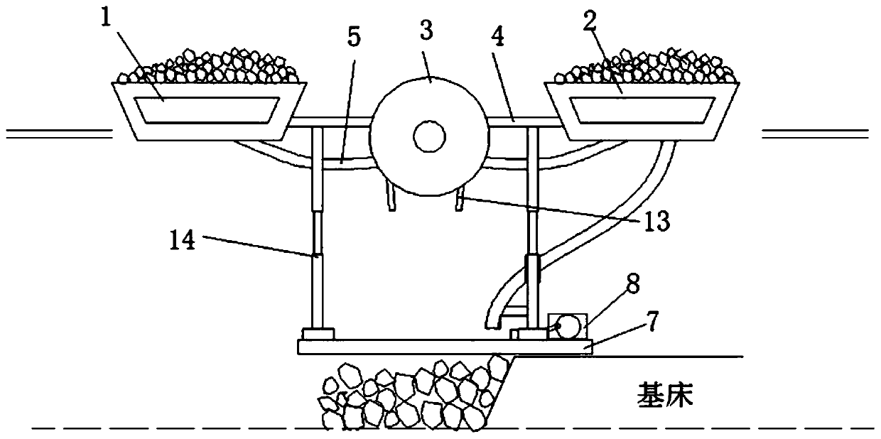
[0030] see Figure 1-3, the present invention provides a technical solution: a construction device for an underwater riprap foundation bed, comprising a left side open-bottom barge 1, a right side open-bottom barge 2, a stone storage device 3, a horizontal track 7, a drive motor 8, Stone grab bucket 16, movable support frame 23 and slider crank mechanism 22, the right side of the left open bottom barge 1 is connected with one end of the connecting rod 4 by bolts and nuts to facilitate the installation of the connecting rod 4, the described The middle part of the connecting rod 4 is provided with a storage stone device 3, which can ensure the stability of the storage stone device 3, and the other end of the connecting rod is connected with the right side open-bottom barge 2; the left side open-bottom barge 1 and The bottom of the open-bottom barge 2 on the right side is respectively connected to the storage stone device 3 through the conveying pipeline 5, and the function of co...

Embodiment 2

[0035] Such as Figure 4 , 6 , 9, this embodiment is a further optimization of embodiment 1, wherein, the middle part of the connecting rod 4 is connected to the storage stone device 3, the storage stone device 3 is a cylinder, and the storage stone device 3 Consisting of an outer shell 10 and an inner shell 11, the end cover on one side of the cylinder that penetrates the storage stone device 3 is provided with the conveying pipelines 5 that are respectively connected to the left open bottom barge 1 and the right open bottom barge 2 The delivery pipe 5 extends to the inner cavity of the inner shell 11; the other end cover center of the storage stone device 3 is provided with a rotating shaft 12 connected with the outer shell 10; the outer shell 10 It can rotate along the rotating shaft 12, which can facilitate the discharge of stones inside the storage stone device 3; the side wall of the inner shell 11 is symmetrically and evenly distributed with two rows of circular holes ...

Embodiment 3

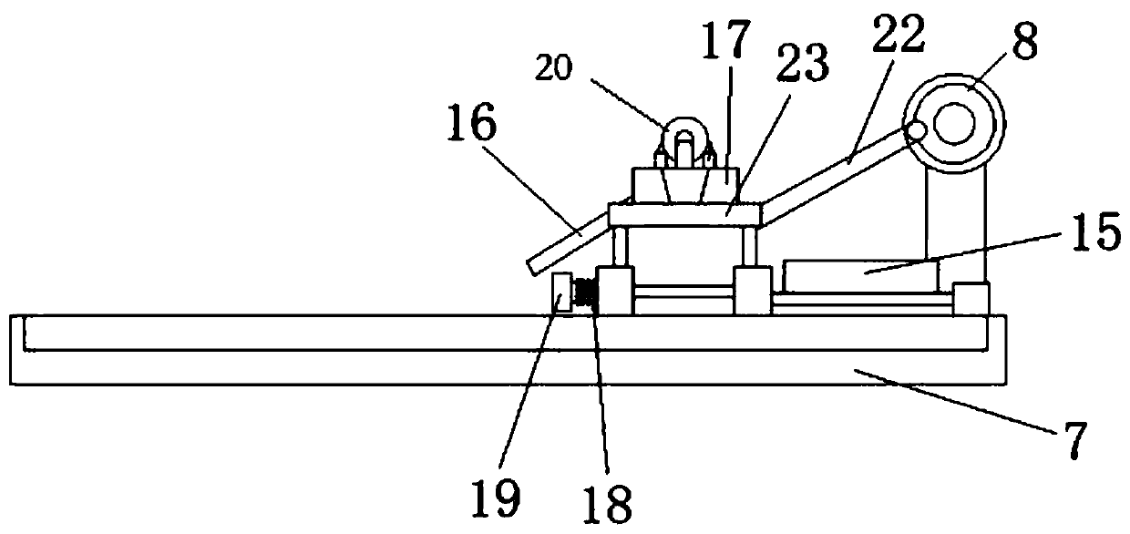
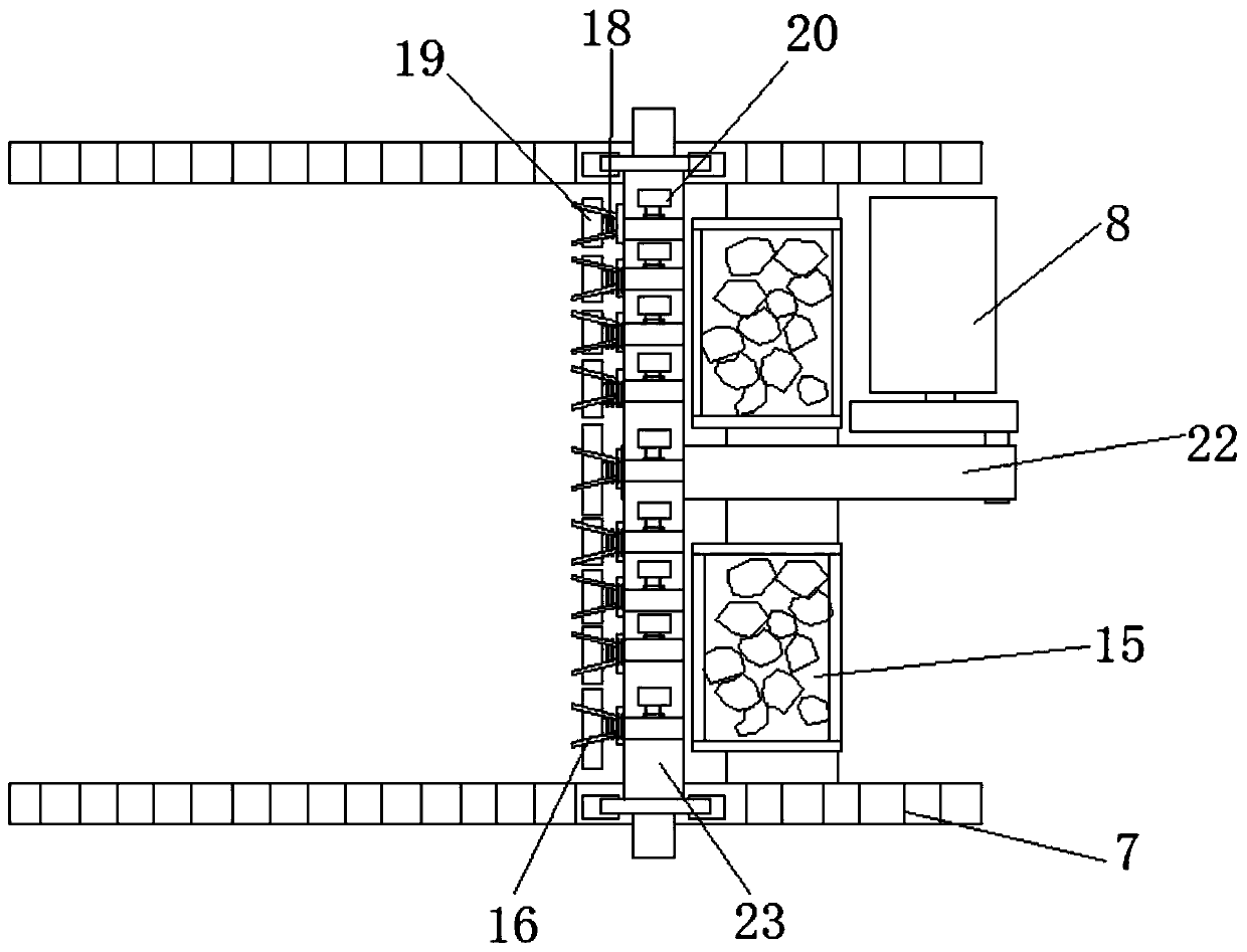
[0039] Such as figure 1 As shown, the difference between this embodiment and Embodiment 1 is that: the bottom of the right open bottom barge 2 is connected with a plurality of spring telescopic tubes, small stones are placed inside the spring telescopic tubes, and on the movable support frame 23 A cross bar (not shown) perpendicular to the horizontal track 7 is provided, and several square fixing rings are arranged on the cross bar, and the spring telescopic tube is fixed to each of the stone grab buckets 16 by the square fixing rings. Above: the spring compression state detection device is connected with the spring telescopic tube valve. The spring 18 is in a semi-compressed state, and uses the flexibility of the spring 18 to control the opening and closing of the valve of the spring telescopic tube.

[0040] As a preferred implementation of this embodiment, such as Figure 5 , 8 As shown, the end of the rock grab 16 is connected with a pneumatic telescopic rod, and the ce...


PUM


Abstract

The invention discloses an underwater riprap foundation bed construction device which comprises a left-side garbage scow, a right-side garbage scow, a stone block storage device, a horizontal track, astone block grab bucket, a movable support frame and a slider-crank mechanism. According to the underwater riprap foundation bed construction device provided by the invention, through arranging the stone block storage device and a rock rip-rap container in the stone block storage device for riprapping, through arranging a baffle plate and a spring on one side of the movable support frame and arranging a stone storage tank on the other side of the movable support frame, and by utilizing the stone block grab bucket for carrying out underwater exact leveling on the riprap foundation bet, stone blocks can be distributed uniformly, so that the occurrence of the phenomenon of nonuniformity in riprapping is effectively avoided, and the follow-up work load is greatly reduced.

Description

technical field [0001] The invention relates to the technical field of construction machinery, in particular to a construction device for an underwater riprap foundation bed. Background technique [0002] When designing and constructing offshore gravity structures, if a gravity structure is used, the foundation is often treated before the construction of the superstructure to form a foundation with high bearing capacity and good durability. The current foundation treatment of gravity hydraulic structures mostly adopts the form of underwater riprap foundation bed. In the construction of underwater riprap foundation bed, artificial riprap or riprap by barge is generally used. After layering and tamping, divers dive into the bottom of the water and use the guide rail method to level the riprap foundation to form a flat foundation with high bearing capacity, thereby preventing the gravity structure from overturning due to the uneven top of the foundation. [0003] Regardless of...

Claims


Application Information

Patent Timeline
Patent Type & Authority Applications(China)
IPC IPC(8): E02D15/10
CPCE02D15/10E02D2250/0061
Inventor 庄宁杨培杰许明宇何良德陈达欧阳锋
Owner HOHAI UNIV
Why Eureka
Try Eureka