Building water supply and drainage device with expanding function

A water supply and drainage, functional technology, applied in water supply installations, buildings, indoor sanitary pipeline installations, etc., can solve the problems of difficult and incomplete cleaning of waste water supply and drainage pipelines

Inactive Publication Date: 2020-07-28
安徽中控建设工程有限公司
View PDF11 Cites 6 Cited by
  • Summary
  • Abstract
  • Description
  • Claims
  • Application Information

AI Technical Summary

Problems solved by technology

[0005] The purpose of the present invention is to propose a building water supply and drainage device with a diastolic function in order to solve the problem that the waste water supply and drainage pipelines in the existing inter-floor construction process are blocked and difficult to clean and not cleaned thoroughly.

Method used


Image

  • Building water supply and drainage device with expanding function
  • Building water supply and drainage device with expanding function
  • Building water supply and drainage device with expanding function

Examples


Embodiment 1

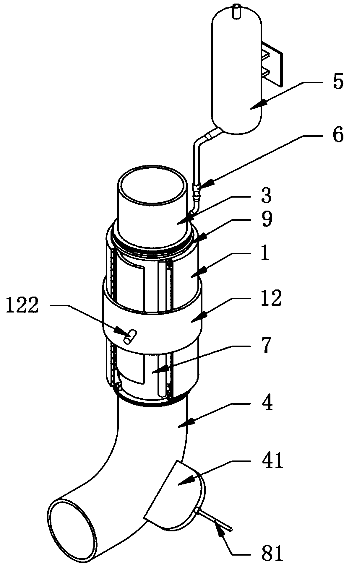
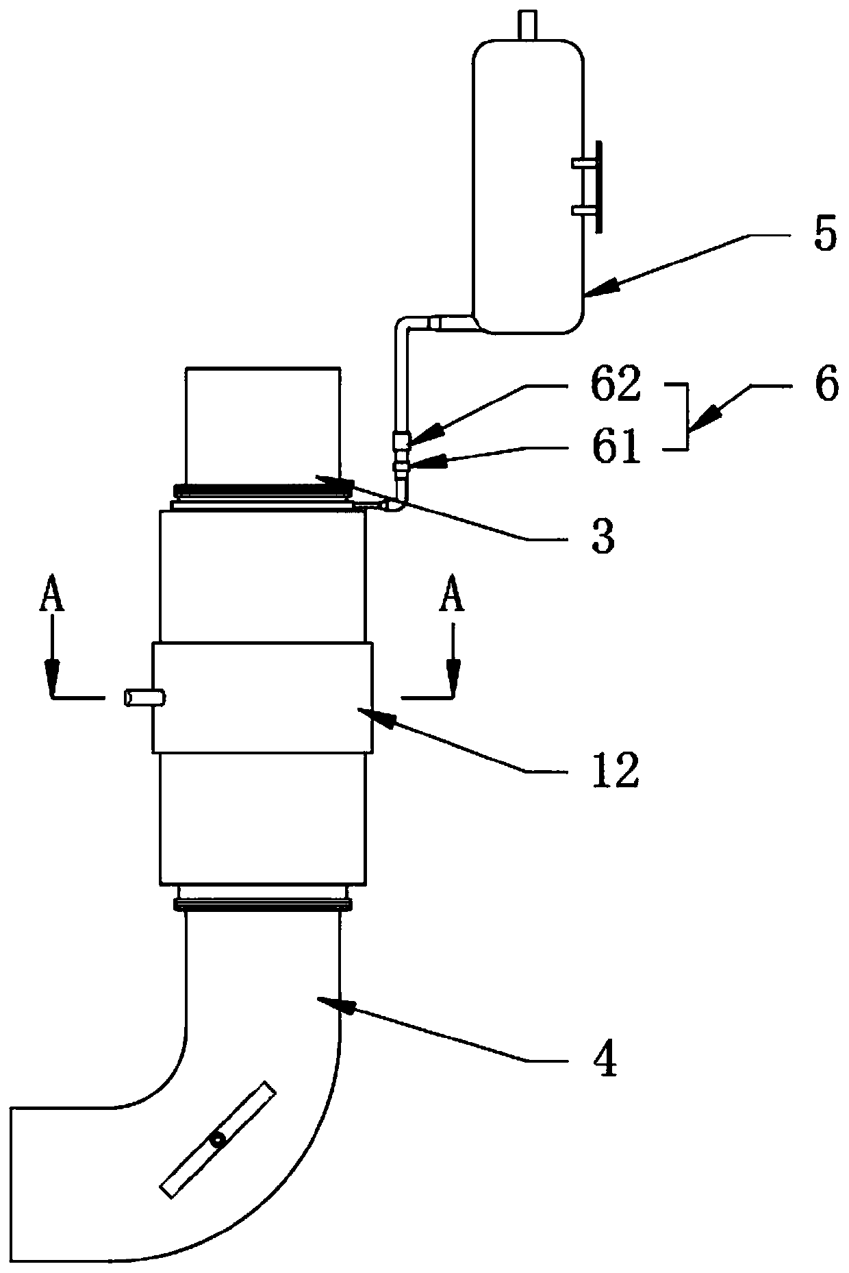
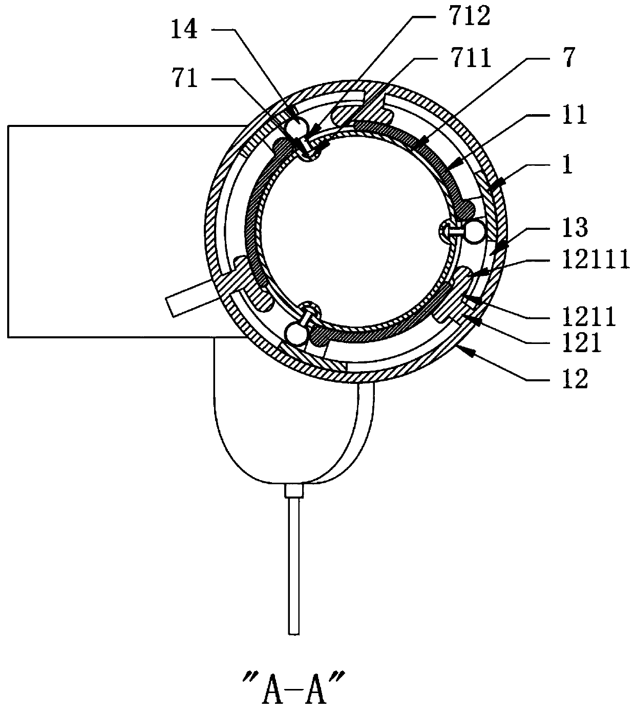
[0040] see Figure 1-9, a building water supply and drainage device with a diastolic function, including a base pipe 1, an upper pipe 3, a lower pipe 4, a water tank 5 and a control valve group 6. During the construction of a high-rise building, drainage pipes need to be embedded between floors. This device It is used to install in the section where the flow rate of the drainage pipe is slow and easy to be blocked, such as the position on the floor of the bathroom and the kitchen between floors. The position of the tube 1; the specific structure of the device is as follows, the upper tube 3 and the lower tube 4 are arranged at the two ends of the base tube 1, and a soft rubber tube 7 is placed in the base tube 1, and the soft rubber tube 7 corresponds to a position that is easy to be blocked. The inner surface wall of the tube 1 is hinged with vertically distributed circular arc plates 11. The number of circular arc plates 11 is at least three and is uniformly distributed in t...

Embodiment 2

[0042] see figure 1 and Figure 10 , the difference from Embodiment 1 is that the lower tube 4 is in the shape of an elbow and a rectangular shell 41 is fixedly arranged on one side of the bent part, one end of the rectangular shell 41 is open and communicates with the inner cavity of the lower tube 4, and the lower tube 4 is provided with The disc 8 is fixedly provided with a connecting shaft 81 on the outer side of the disc 8, and one end of the connecting shaft 81 runs through the other end of the rectangular shell 41 and is for rotation and axial sliding fit. In this embodiment, in the initial state, the disc 8 is located in the rectangular shell 41. When accumulation occurs at the bend, the connecting shaft 81 is manually slid, and the disc 8 is located in the middle of the bend of the lower tube 4. By rotating the connecting shaft 81, The disk 8 rotates at the curved part, and then can scrape the inner wall of the curved part of the lower pipe 4. The outer periphery of ...

Embodiment 3

[0044] see Figure 4 , Figure 5 and Figure 7-9 , the further description relative to Embodiment 1 is that the two ends of the base pipe 1 are fixedly provided with a connecting pipe 15 having an inner diameter equal to that of the soft rubber pipe 7, and a through hole 16 is opened on one side of the connecting pipe 15, and the rubber water storage pipe 14 The two ends are fixedly provided with positioning short pipes 141 passing through the through hole 16, the two ends of the soft rubber pipe 7 are fixedly provided with annular plates 72, the connecting pipe 15 is connected with the upper pipe 3 and the lower pipe 4 through a clamp, and the water spray pipe 71 The two ends of the upper tube 3 and the lower tube 4 are snap-connected. Specifically, snap rings can be fixed on the inner surface walls of the upper tube 3 and the lower tube 4. The tops of a plurality of positioning short tubes 141 are detachably connected with sleeves on the connecting tubes. The ring-shaped w...


PUM


Abstract

The invention discloses a building water supply and drainage device with an expanding function. The building water supply and drainage device with the expanding function comprises a basic pipe, an upper pipe, a lower pipe, a water tank and a control valve set. According to the building water supply and drainage device with the expanding function, the basic pipe is arranged, a soft rubber pipe is accommodated in the basic pipe, the soft rubber pipe corresponds to a part easy to block, circular arc plates which are uniformly distributed in the circumferential direction are hinged to the internalsurface wall of the basic pipe, rubber water storage pipes are arranged between the adjacent circular arc plates, wherein the internal surface wall of the soft rubber pipe is fixedly connected with awater spray pipe, the water spray pipe communicates with the rubber water storage pipes outside, a driving sleeve is rotationally connected outside the basic pipe, and shifting plates positioned on one sides of the circular arc plates are fixedly connected to the internal surface wall of the driving sleeve; and therefore, when the driving sleeve rotates, the shifting plates rotate to drive the circular arc plates to rotate through shifting columns arranged on the shifting plates so as to peel off blockage piled in the soft rubber pipe; and moreover, a function of extruding the blockage into clusters is also realized to facilitate the discharging of the blockage; and as the driving sleeve reversely rotates, the shifting plates extrude the rubber water storage pipes, and the water spray pipe sprays water into the soft rubber pipe, a washing effect is realized.

Description

technical field [0001] The invention relates to the technical field of construction engineering, in particular to a building water supply and drainage device with diastolic function. Background technique [0002] During the construction of high-rise buildings, the walls between floors need to be sprayed and painted, and in rainy days, water will accumulate on the ground between floors, which will generate construction mixed wastewater. Therefore, it is necessary to install water supply and drainage pipes indoors for discharge waste water. [0003] At present, for the water supply and drainage pipes used in building construction, they are usually a single PVC pipe structure and equipped with high-pressure flushing equipment. Blockage, it is difficult to clean up after the blockage and the cleaning is not thorough, which will affect the construction. [0004] Therefore, the present invention provides a building water supply and drainage device with relaxation function. Con...

Claims


Application Information

Patent Timeline
Patent Type & Authority Applications(China)
IPC IPC(8): E03C1/122E03C1/30E03C1/304
CPCE03C1/122E03C1/1222E03C1/30E03C1/304
Inventor 王小雨
Owner 安徽中控建设工程有限公司
Why Eureka
Try Eureka