
A non-destructive testing device for welded pipe joints

A technology of non-destructive flaw detection and welded pipes, which is applied in the direction of measuring devices, engine lubrication, instruments, etc., can solve the problems of high work intensity, reduced work efficiency, and low detection efficiency

Active Publication Date: 2020-10-23
NINGBO MINGFENG INSPECTION & TESTING RES INST CO LTD
View PDF6 Cites 0 Cited by
  • Summary
  • Abstract
  • Description
  • Claims
  • Application Information

AI Technical Summary

Problems solved by technology

[0003] In the current non-destructive inspection of the welded position of the pipeline, the staff needs to manually push the flaw detector so that the flaw detector moves on the pipeline to check the welded part, but the detection efficiency is low. At the same time, when inspecting the bottom of the pipeline, it is necessary to rotate the pipeline , the work intensity is high, reducing work efficiency

Method used


Image

  • A non-destructive testing device for welded pipe joints
  • A non-destructive testing device for welded pipe joints
  • A non-destructive testing device for welded pipe joints

Examples


Embodiment

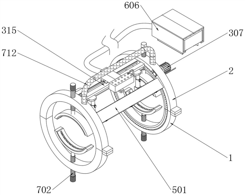
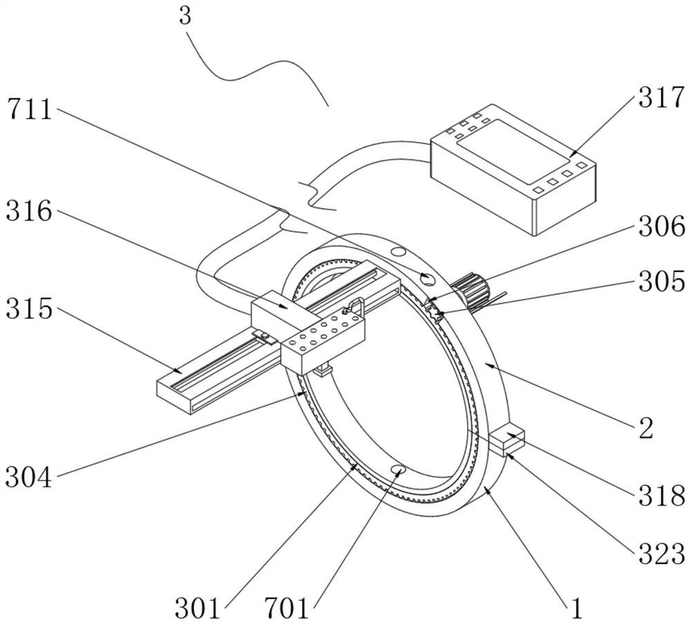
[0050] Example: such as Figure 1-10 As shown, the present invention provides a technical solution, a non-destructive flaw detection device for welded pipe joints, including two limiting rings 1 and two fixing rings 2, and one end of the adjacent limiting ring 1 is hinged with a fixing ring 2;

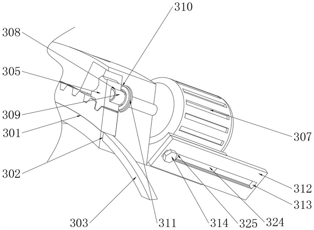
[0051] One end of the fixed ring 2 is equipped with a detection and fixing assembly 3, and the detection and fixing assembly 3 includes an installation groove 301, a limit groove 302, a limit ring 303, a ring gear 304, a gear 305, a gear groove 306, a driving motor 307, a driving groove 308, a rubber Cylinder 309, fixed card slot 310, collar 311, fixed plate 312, moving slot 313, limit screw 314, horizontal support platform 315, flaw detector 316, observer 317, fixed block 318, insertion column 319, movable plate 320, Connect the spring 321, the clamping plate 322, the corresponding block 323, the motor fixing seat 324, the T-shaped block 325 and the corresponding hole 326;

[0052] O...


PUM


Abstract

The invention discloses a nondestructive flaw detection device of a welded pipe joint. The nondestructive flaw detection device of the welded pipe joint comprises two limiting rings and two fixing rings. One end of each limiting ring and one end of each fixing ring are both provided with installation grooves. The bottom ends of the installation groove on one limiting ring and the installation groove on one fixing ring are provided with limiting grooves, a limiting ring is installed in the limiting grooves in an embedded manner, the top end of the limiting ring is located in the installation grooves and provided with a toothed ring in a welded manner, a gear is meshed with one side of the top end of the toothed ring, one side of the fixing ring is provided with a gear groove corresponding to the gear in position, a drive motor is movably installed at one end of the fixing ring, one end of the gear is provided with a drive groove corresponding to an output shaft of the drive motor, one end of the toothed ring is provided with a horizontal supporting platform through a rotating shaft, a flaw detector is movably installed at the top end of the horizontal supporting platform, one end ofthe flaw detector is connected with a viewer. Work personnel do not need to manually push the flaw detector to conduct detection, the problems existing in the background technology are solved, the work personnel do not need to rotate the pipeline, the safety coefficient of the work personnel is improved, and the needed detection time is shortened.

Description

technical field [0001] The invention relates to the technical field of nondestructive flaw detection of welded pipes, in particular to a nondestructive flaw detection device for welded pipe joints. Background technique [0002] To detect cracks or defects inside metal materials or components, the commonly used flaw detection methods are: X-ray flaw detection, ultrasonic flaw detection, magnetic particle flaw detection, penetrant flaw detection, eddy current flaw detection, gamma ray flaw detection, physical flaw detection is non-destructive without chemical changes Flaw detection, after the welding of the pipeline is completed, non-destructive flaw detection is required at the welding position. [0003] In the current non-destructive inspection of the welding position of the pipeline, the staff needs to manually push the flaw detector to make the flaw detector move on the pipeline to check the welded part, but the detection efficiency is low. At the same time, when inspectin...

Claims


Application Information

Patent Timeline
Patent Type & Authority Patents(China)
IPC IPC(8): F16M13/02F16M11/18F16M11/04F16N11/08G01N33/2045
CPCF16M11/04F16M11/18F16M13/022F16N11/08G01N33/2045
Inventor 张群花
Owner NINGBO MINGFENG INSPECTION & TESTING RES INST CO LTD
Learn More