Supercharge Your Innovation With Domain-Expert AI Agents!

Preparation method of LED lamp

A technology of LED lamps and LED lamp beads, which is applied in the direction of electrical components, circuits, semiconductor devices, etc., can solve the problems of large time difference, inability to accurately reflect the temperature of the LED chip, and the need for a certain period of time to respond, and achieve a simplified structure The effect of the layout

Active Publication Date: 2020-07-28
福建省信达光电科技有限公司
View PDF16 Cites 1 Cited by
  • Summary
  • Abstract
  • Description
  • Claims
  • Application Information

AI Technical Summary

Problems solved by technology

However, because the LED chip is the heat source, the heat emitted by the LED chip as the heat source is transmitted outward, the farther the distance is, the lower the temperature is, even if the temperature compensation is made, it cannot accurately reflect the real temperature of the LED chip; Or, after the temperature of the LED chip changes, it often takes a certain amount of time for the outside world (the surface of the LED lamp bead or the packaging substrate) to react, and the transmission time difference is large, so timely monitoring cannot be realized

Method used


Image

  • Preparation method of LED lamp
  • Preparation method of LED lamp
  • Preparation method of LED lamp

Examples


Embodiment 1

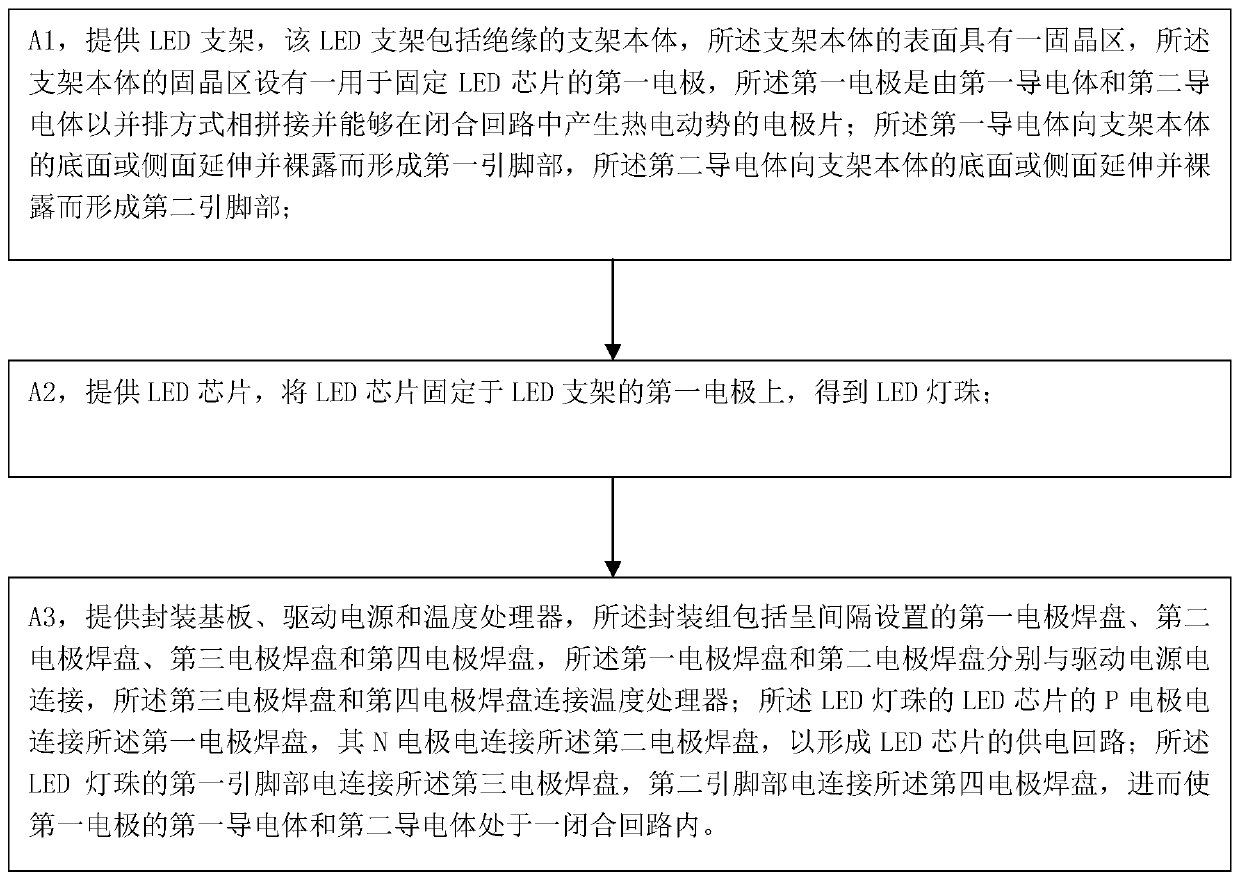
[0033] Reference figure 1 As shown, a method for manufacturing an LED lamp includes the following steps:

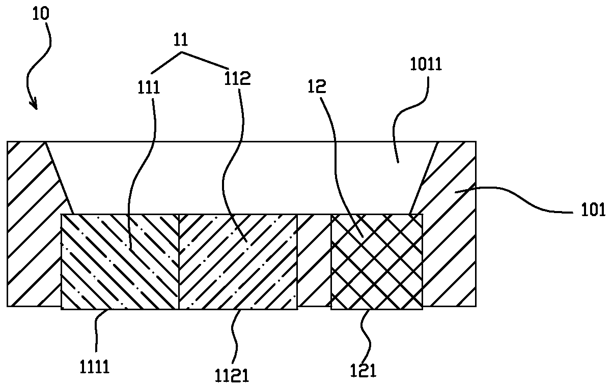
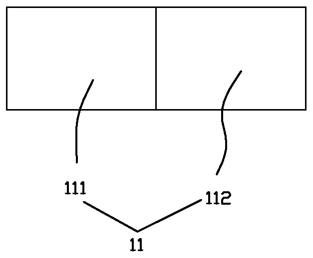
[0034] A1, provide LED bracket, refer to figure 2 , image 3 As shown, the LED stent includes an insulated stent body, the surface of the stent body has a die-bonding area, and the die-attachment area of ​​the stent body is provided with a first electrode for fixing the LED chip. The first electrode is An electrode sheet that is spliced ​​side by side by a first electrical conductor and a second electrical conductor and can generate thermoelectromotive force in a closed loop; the first electrical conductor faces the bottom surface of the support body (in other embodiments, it may also be a side surface) Extending and being exposed to form a first lead part, and the second conductive body extends to the bottom surface (or a side surface in other embodiments) of the support body and being exposed to form a second lead part.

[0035] Specifically, the die-bonding zone of this st...

Embodiment 2

[0054] The preparation method of the LED lamp provided in this embodiment is roughly the same as the preparation method of the first embodiment, the difference is:

[0055] In step A1, refer to Figure 7 As shown, the die bonding area of ​​the holder body 101 is provided with a second electrode 12 and a third electrode 13 as positive and negative electrodes, and the second electrode 12 faces the bottom surface of the holder body 101 (in other embodiments, it may also It is a side surface) extending and exposed to form a third pin portion 121, and the third electrode 13 extends to the bottom surface (or a side surface in other embodiments) of the holder body 101 and is exposed to form a fourth pin portion 131. The first electrode 11 only serves as an electrode for fixing the LED chip 21.

[0056] Meanwhile, the first electrical conductor 111 of the first electrode 11 is a nickel-chromium alloy, and the second electrical conductor 112 is a copper-nickel alloy. After the first electr...


PUM


Abstract

The invention provides a preparation method of a LED lamp. The method comprises the following steps: A1, providing an LED bracket provided with a first electrode used for fixing an LED chip, wherein the first electrode is an electrode sheet which is formed by splicing a first electric conductor and a second electric conductor side by side and can generate thermoelectromotive force in a closed loop; A2, fixing an LED chip on the first electrode of the LED bracket; and A3, providing a packaging substrate, a driving power supply and a temperature processor, wherein a first electrode bonding pad and a second electrode bonding pad of the packaging substrate are electrically connected with the driving power supply, a third electrode bonding pad and a fourth electrode bonding pad of the packagingsubstrate are connected with the temperature processor, the P electrode of the LED chip is electrically connected with the first electrode bonding pad, the N electrode of the LED chip is electricallyconnected with the second electrode bonding pad, the first pin part of the LED lamp bead is electrically connected with the third electrode bonding pad, and the second pin part of the LED lamp bead is electrically connected with the fourth electrode bonding pad.

Description

Technical field [0001] The invention relates to the field of LED lighting, in particular to a method for preparing an LED lamp. Background technique [0002] At present, there are many types of LED brackets on the market, and most of them are packaged with a bracket with two metal electrodes. Or adopt three or more metal electrodes in the form of thermoelectric separation. During die bonding, the LED chip is fixed on the corresponding metal bracket, and then a series of processes such as "wire bonding-dispensing-baking-screening-packaging" are carried out to make finished LED lamp beads. [0003] However, because LED lamp beads are more sensitive to temperature, for example, for a chip with a size of about 10mil*30mil, when the current is 100mA, the brightness of the whole lamp will decrease by 1% every time the temperature of the whole lamp rises by 4.73℃. As the used current increases, its sensitivity to temperature will further increase, and the brightness will decrease accord...

Claims


Application Information

Patent Timeline
Patent Type & Authority Applications(China)
IPC IPC(8): H01L33/48H01L33/62H01L33/64
CPCH01L33/483H01L33/62H01L33/647H01L2933/0033H01L2933/0075
Inventor 田晓波谢剑平罗晓东杜涛刘亚男
Owner 福建省信达光电科技有限公司
Features
  • R&D
  • Intellectual Property
  • Life Sciences
  • Materials
  • Tech Scout
  • Unparalleled Data Quality
  • Higher Quality Content
  • 60% Fewer Hallucinations
Learn More