
Switching state control method, control circuit and flyback converter

A flyback converter and switching state technology, which is applied in the direction of adjusting electrical variables, control/regulation systems, high-efficiency power electronic conversion, etc., can solve problems such as large switching loss, generation of circulating current, excessive negative current, etc.

Active Publication Date: 2020-07-28
西安矽力杰半导体技术有限公司
View PDF6 Cites 2 Cited by
  • Summary
  • Abstract
  • Description
  • Claims
  • Application Information

AI Technical Summary

Problems solved by technology

Currently commonly used control methods, one is to detect the drain-source voltage of the synchronous rectifier and compare it with a fixed reference, but this cannot guarantee zero-voltage turn-on under different input voltages.
As a result, when low voltage is input, the negative current is too large, resulting in circulating current; when high voltage is input, the negative current is not enough, and when the drain-source voltage is still relatively high, the primary power tube is turned on, and the switching loss is still relatively large

Method used


Image

  • Switching state control method, control circuit and flyback converter
  • Switching state control method, control circuit and flyback converter
  • Switching state control method, control circuit and flyback converter

Examples


Embodiment Construction

[0045] The present invention is described below based on examples, but the present invention is not limited to these examples. In the following detailed description of the invention, some specific details are set forth in detail. The present invention can be fully understood by those skilled in the art without the description of these detailed parts. In order not to obscure the essence of the present invention, well-known methods, procedures, procedures, components and circuits have not been described in detail.

[0046] Additionally, those of ordinary skill in the art will appreciate that the drawings provided herein are for illustrative purposes and are not necessarily drawn to scale.

[0047] Meanwhile, it should be understood that in the following description, "circuit" refers to a conductive loop formed by at least one element or sub-circuit through electrical connection or electromagnetic connection. When an element or circuit is said to be "connected to" another eleme...


PUM


Abstract

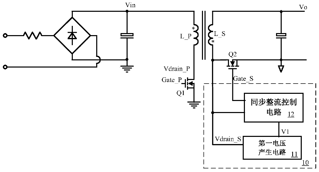
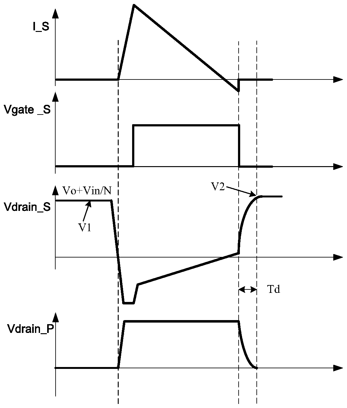
The invention discloses a switching state control circuit, a switching state control method and a flyback converter. A first voltage sampling signal representing the input voltage information is obtained, the conduction time of a synchronous rectifier tube is adjusted according to a change state of the first voltage sampling signal so as to adjust an absolute value of the negative current flowingthrough a secondary winding, and the negative current is used for discharging a junction capacitor of a main power tube and reducing a drain-source voltage of the main power tube. Under different input voltages, ZVS switching-on of the main power tube can be realized, the negative current is proper, no redundant circulation is generated, and self-adaptive control is realized.

Description

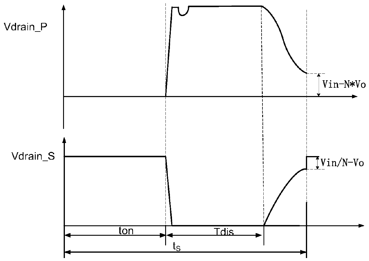
technical field [0001] The invention relates to a power electronic technology, more specifically, to a switch state control method, a control circuit and a flyback converter applied in a switching power supply. Background technique [0002] When the flyback converter works in the quasi-resonant state (QR), when the freewheeling current of the secondary side ends, resonance occurs between the magnetizing inductance of the transformer and the junction capacitance of the main power tube, and the resonance waveform is as follows: figure 1 As shown, in order to reduce the loss of the main power transistor Q1, the conduction of the main power transistor is usually controlled when the drain-source voltage Vdrain_P is at the bottom, that is, the main power transistor Q1 of the primary side is turned on when the drain-source voltage drops to the lowest point. However, the lowest point of its free resonance is Vin-NVo (Vin is the input voltage of the converter, Vo is the output voltag...

Claims


Application Information

Patent Timeline
Patent Type & Authority Applications(China)
IPC IPC(8): H02M3/335H02M7/217
CPCH02M3/33592H02M7/217H02M1/0025H02M1/0009H02M1/0058H02M1/08
Inventor 胡志亮黄秋凯李新磊白永江
Owner 西安矽力杰半导体技术有限公司
Learn More