Supercharge Your Innovation With Domain-Expert AI Agents!

Efficient heat dissipation mechanism of inverter device

A technology of a heat dissipation mechanism and an inverter, which is applied in the output power conversion device, the structural parts of the conversion equipment, and the modification of power electronics, etc. Efficient cooling effect

Inactive Publication Date: 2020-07-28
林闽华
View PDF0 Cites 0 Cited by
  • Summary
  • Abstract
  • Description
  • Claims
  • Application Information

AI Technical Summary

Problems solved by technology

[0003] The structure of the heat dissipation mechanism in the prior art is simple, and a single fan is usually used for heat dissipation. When the inverter is used for a long time, the heat dissipation effect is not good, and the temperature drops slowly. It is easy to cause voltage instability and electronic The components are burned, and the external dust is easy to enter the equipment, which affects the normal use of the equipment

Method used


Image

  • Efficient heat dissipation mechanism of inverter device
  • Efficient heat dissipation mechanism of inverter device
  • Efficient heat dissipation mechanism of inverter device

Examples


Embodiment 1

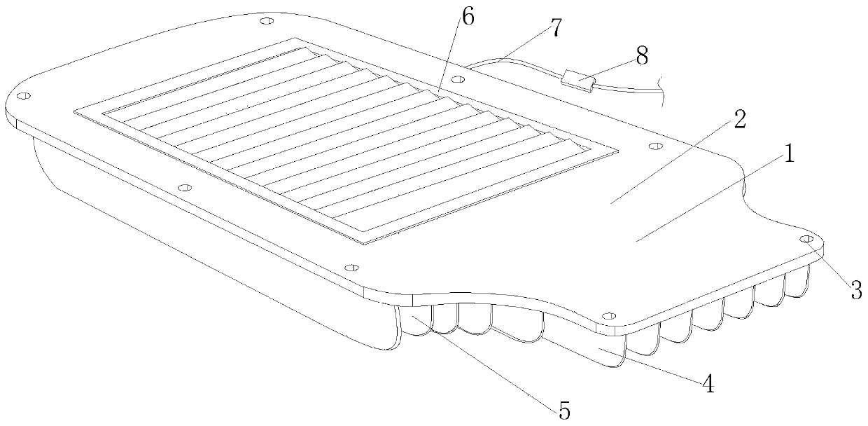
[0030] see figure 1 , a high-efficiency heat dissipation mechanism for an inverter device of the present invention, the heat dissipation body 1 includes a main frame 2, a fixing hole 3, a long heat conduction sheet 4, a short heat conduction sheet 5, an air cooling structure 6, a power cord 7 and a control switch 8, There are eight fixing holes 3 at equal distances on the outside of the main frame 2. Long heat conducting fins 4 are vertically embedded in the middle side of the bottom of the main frame 2. Short heat conducting fins 5 are vertically embedded on the left and right sides of the bottom of the main frame 2. The side is embedded with an air-cooling structure 6, and the left side of the rear of the main frame 2 is provided with a power cord 7, and a control switch 8 is installed on the inner side of the power cord 7. The air-cooling structure 6 can quickly dissipate heat from the inverter, and can effectively block External dust enters the inverter.

[0031] see fi...

Embodiment 2

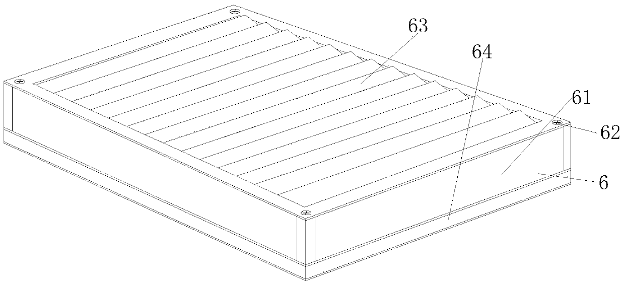
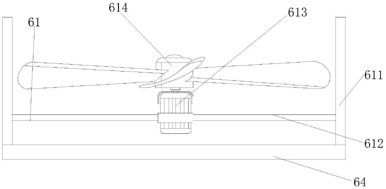
[0038] In the high-efficiency heat dissipation mechanism of the inverter device of the present invention, there are fourteen sheets 6331 in total, and the fourteen sheets 6331 are equidistantly arranged inside the rectangular frame sheet 631, and the air flow is changed by the fourteen sheets 6331 According to the size of the passage, the rotating shaft rod 6332 is inserted into the inner side of the rotating hole 6322 and connected to it in rotation. The sheet body 6331 is rotated through the rotating shaft rod 6332. The rectangular block 6333 is inserted into the inner side of the card slot 6324 and engaged with it. The cooperation between the grooves 6324 changes the rotation angle of the sheet body 6331, the brush 6334 at the bottom of the sheet body 6331 is in contact with the top of the other sheet body 6331, and the brush 6334 removes the dust on the other sheet body 6331 when the sheet body 6331 rotates. Brush down.

[0039] The present invention provides a high-effici...


PUM


Abstract

The invention discloses an efficient heat dissipation mechanism of an inverter device. The efficient heat dissipation mechanism of the inverter device comprises a main frame, a fixing hole, a long heat conduction sheet, a short heat conduction sheet, an air cooling structure, a power line and a control switch. By optimizing the air cooling structure, cooling liquid in a heat conduction pipe circularly flows under the action of a small water pump to absorb heat, an electric motor is used as a power source to drive fan blades to rotate to generate airflow to blow the heat to the outside, a sheetbody can rotate under the action of a driving motor to adjust the size of an air port so as to perform efficient heat dissipation, moreover, a brush at the bottom of the sheet body can shield dust inthe air, so problems that an inverter is poor in heat dissipation effect and slow in temperature drop after long-time use, the voltage is easily unstable when the inverter is in a high-temperature environment for a long time, electronic components are easily burnt out, external dust easily enters equipment, and normal use of the equipment is influenced are solved.

Description

technical field [0001] The invention relates to the related field of inverters, in particular to an efficient heat dissipation mechanism of an inverter device. Background technique [0002] Most of the use of electronic products in our daily life uses switching power supplies or other rectification circuits to convert alternating current into direct current through 220V alternating current. The so-called inverter is the process of converting direct current into alternating current. It is a rectification conversion The reverse process is called an inverter; a heat dissipation mechanism is usually installed inside the inverter to absorb the heat generated during operation and prevent the inverter from being burned due to excessive heat. [0003] The structure of the heat dissipation mechanism in the prior art is simple, and a single fan is usually used for heat dissipation. When the inverter is used for a long time, the heat dissipation effect is not good, and the temperature ...

Claims


Application Information

Patent Timeline
Patent Type & Authority Applications(China)
IPC IPC(8): H05K7/20H02M7/00
CPCH02M7/003H05K7/20181H05K7/2089H05K7/20909H05K7/20927
Inventor 林闽华
Owner 林闽华
Features
  • R&D
  • Intellectual Property
  • Life Sciences
  • Materials
  • Tech Scout
  • Unparalleled Data Quality
  • Higher Quality Content
  • 60% Fewer Hallucinations
Learn More