Insulator iron cap quality detection device

A detection device and insulator technology, applied in sorting and other directions, can solve the problems of sorting effect, affecting work process, low work efficiency, etc., and achieve the effect of reducing manual operation, improving use effect, and efficient sorting and collection.

Inactive Publication Date: 2020-07-31
刘常斌
View PDF6 Cites 0 Cited by
  • Summary
  • Abstract
  • Description
  • Claims
  • Application Information

AI Technical Summary

Problems solved by technology

[0002] An insulator is a special insulation control that can play an important role in overhead transmission lines. The insulator iron cap quality inspection device is a mechanical device used for the actual use quality inspection of insulator iron caps. However, in the prior art Due to the large number of iron caps to be detected, it is necessary to use the existing lifting equipment to store the lifting of the iron cap device to be detected, so that the iron caps to be detected can be effectively injected into the detection equipment, and this method makes the actual material of the equipment more inconvenient. At the same time, during the iron cap detection, it is necessary to manually place the iron caps one by one, so that the detection device can effectively detect the quality of the iron caps. Effective sorting can only be carried out after a long distance, so that defective products and finished products may be mixed due to the vibration of the equipment during the sorting process, which will affect the actual sorting effect and affect the overall work process

Method used


Image

  • Insulator iron cap quality detection device
  • Insulator iron cap quality detection device
  • Insulator iron cap quality detection device

Examples


Embodiment Construction

[0017] The following will clearly and completely describe the technical solutions in the embodiments of the present invention with reference to the accompanying drawings in the embodiments of the present invention. Obviously, the described embodiments are only some, not all, embodiments of the present invention.

[0018] Examples of the described embodiments are shown in the drawings, wherein like or similar reference numerals designate like or similar elements or elements having the same or similar functions throughout. The embodiments described below by referring to the figures are exemplary and are intended to explain the present invention and should not be construed as limiting the present invention.

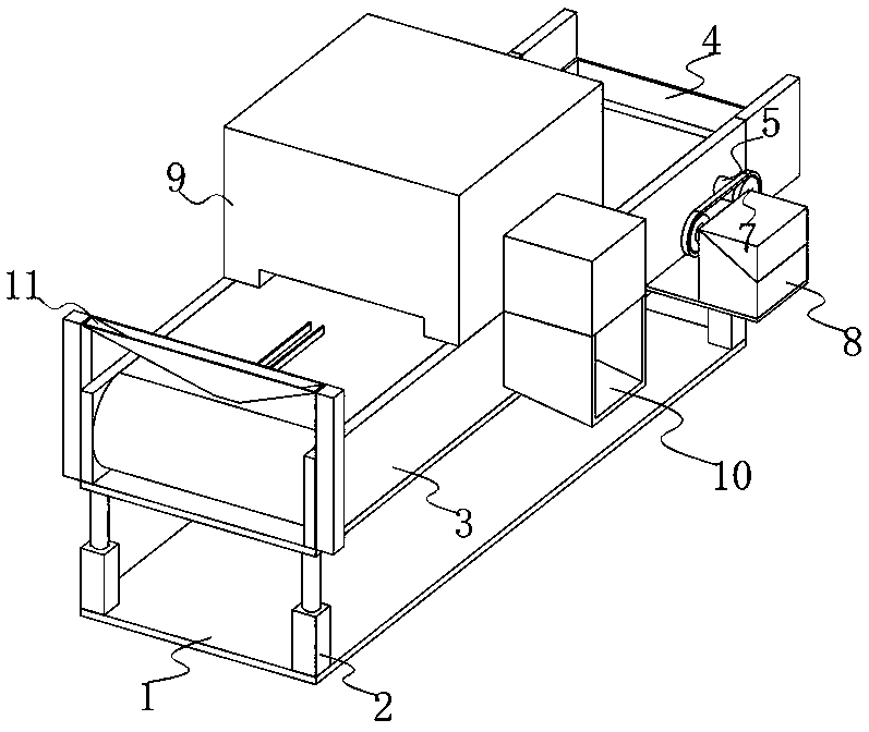
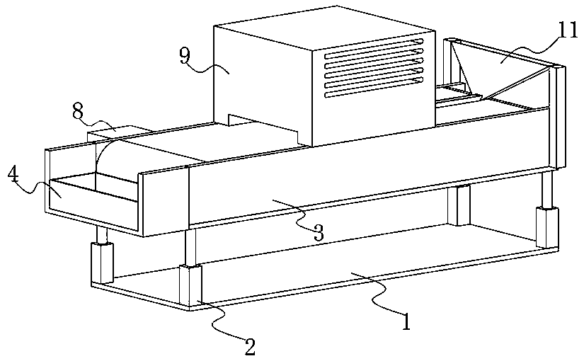
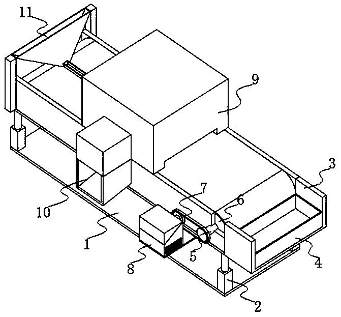
[0019] see Figure 1-3 , the present invention provides a technical solution: an insulator iron cap quality detection device, including a bottom plate 1, the top of the bottom plate 1 near the four corners is provided with air pressure rods 2, and the top ends of the four ai...


PUM


Abstract

The invention discloses an insulator iron cap quality detection device, and relates to the technical field of detection equipment. The insulator iron cap quality detection device comprises a bottom plate, air pressure rods are arranged at the positions, close to four corners, of the top of the bottom plate, a mounting frame is welded between the top ends of the four air pressure rods, supporting shafts are arranged between the inner surface walls of the two sides of the mounting frame and close to the edges of the two sides, a supporting plate is welded to the outer surface of one side of themounting frame and close to the side edge, and a motor box is arranged at the top of the supporting plate and close to the side edge. When the insulator iron cap quality detection device is used, a to-be-detected iron cap is effectively placed in a material injection frame, the iron cap slowly and orderly falls onto the surface of a conveying belt in the material injection frame through vibrationgenerated by actual operation of equipment, the iron cap is effectively conveyed into the detection device body through the conveying belt for detection, defective products are effectively dischargedfrom the conveying belt through a material guide frame, and qualified products effectively fall into the collecting frame through a conveying belt.

Description

technical field [0001] The invention relates to the technical field of detection equipment, in particular to an insulator iron cap quality detection device. Background technique [0002] An insulator is a special insulation control that can play an important role in overhead transmission lines. The insulator iron cap quality inspection device is a mechanical device used for the actual use quality inspection of insulator iron caps. However, in the prior art Due to the large number of iron caps to be detected, it is necessary to use the existing lifting equipment to store the lifting of the iron cap device to be detected, so that the iron caps to be detected can be effectively injected into the detection equipment, and this method makes the actual material of the equipment more inconvenient. At the same time, during the iron cap detection, it is necessary to manually place the iron caps one by one, so that the detection device can effectively detect the quality of the iron cap...

Claims


Application Information

Patent Timeline
Patent Type & Authority Applications(China)
IPC IPC(8): B07C5/00B07C5/02B07C5/36
CPCB07C5/00B07C5/02B07C5/362
Inventor 杨爱德徐桂玲刘常斌何立斌杨伟超
Owner 刘常斌
Why Eureka
Try Eureka