Slurry processing system for injection moulding process

A technology of injection molding process and processing system, which is applied in the field of slurry processing system for injection molding process, can solve problems such as no mention of difficult problems, inability to carry out grinding treatment, affecting the internal density of products, etc., and achieve the effect of ensuring quality

Inactive Publication Date: 2020-07-31
杭州富阳华美五金塑料厂
View PDF0 Cites 3 Cited by
  • Summary
  • Abstract
  • Description
  • Claims
  • Application Information

AI Technical Summary

Problems solved by technology

[0003] However, in the existing injection molding process, the following problems exist in the slurry mixing process, a. The existing mixing equipment can only prevent the slurry from coagulating in a large area by rotating and stirring in the process of mixing the slurry. Large particles cannot be completely removed, which affects the density inside the product after injection molding, causing the molded product to fail to meet the specified standards. b. The traditional mixing equipment uniformly mixes the slurry during operation, and cannot finely refine the slurry Quantitative batch processing, it is impossible to grind the particles with too large crystals inside the slurry, and the processing and stirring effect is poor
[0004] For the technical problems existing in the current injection molding process, personnel in the relevant technical field have made appropriate improvements after research, such as a Chinese utility model patent with a patent number of 2017216630626, a slurry stirring and lifting device, which can save Cost, improve the efficiency of mixing, but the problems in the molding process mentioned above are not mentioned

Method used


Image

  • Slurry processing system for injection moulding process
  • Slurry processing system for injection moulding process
  • Slurry processing system for injection moulding process

Examples


Embodiment Construction

[0024] The embodiments of the present invention will be described in detail below with reference to the accompanying drawings, but the present invention can be implemented in many different ways defined and covered by the claims.

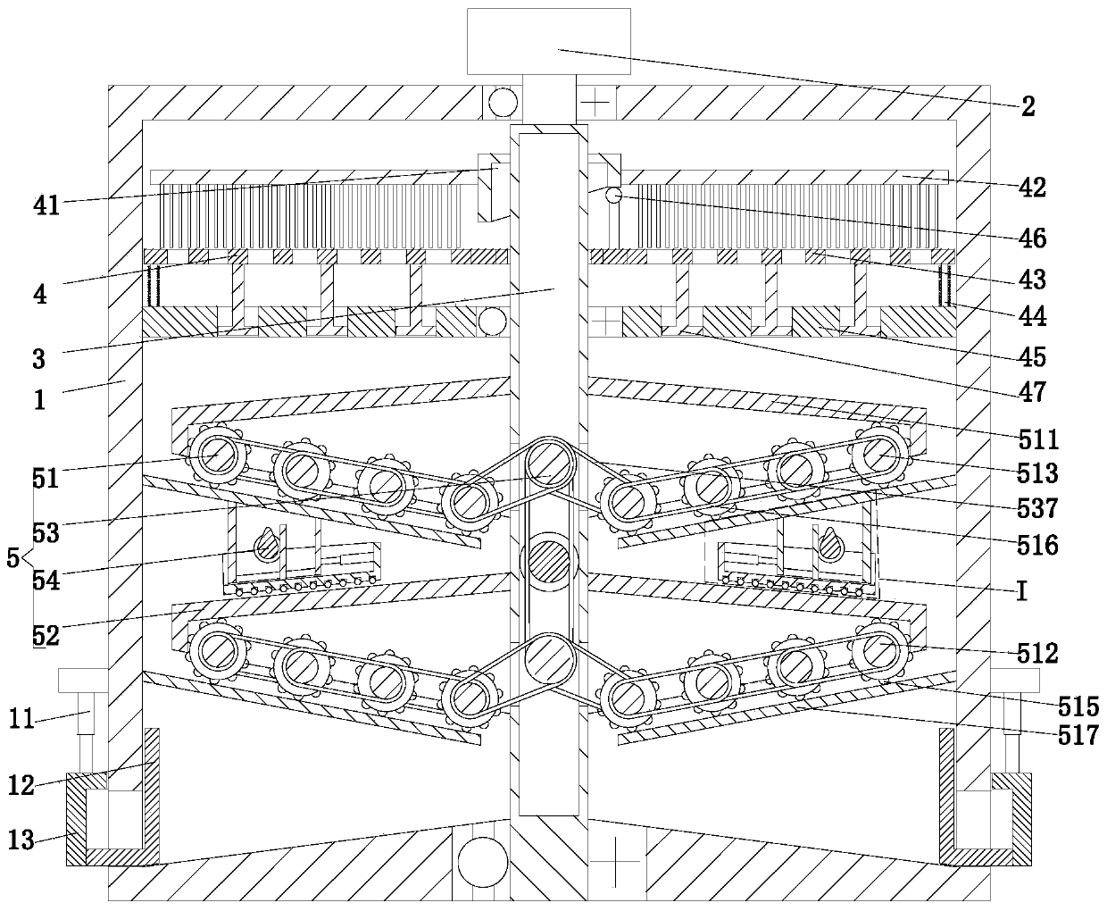
[0025] Such as Figure 1 to Figure 4 As shown, a slurry processing system for injection molding process includes a mixing tank 1, a stirring shaft 2 is connected between the inner walls of the upper and lower ends of the mixing tank 1 through bearings, and the upper end of the stirring shaft 2 passes through the mixing tank 1 and the stirring motor 3 Connected, the stirring motor 3 is installed on the outer wall of the mixing barrel 1 through the motor base, the stirring shaft 2 has a hollow structure, and the stirring shaft 2 is sequentially provided with a crushing mechanism 4 and a grinding mechanism 5 from top to bottom;

[0026] Described crushing mechanism 4 comprises the driving ring 41 that is installed on the outer wall of stirring shaft 2,...


PUM


Abstract

The invention relate to a slurry processing system for an injection moulding process. The slurry processing system comprises a stirring barrel, wherein a stirring shaft is connected between inner walls of upper and lower ends of the stirring barrel through a bearing; and the stirring shaft is sequentially provided with a crushing mechanism and a grinding mechanism from top to bottom. The slurry processing system can solve the problems, in slurry stirring and processing, of an existing injection moulding process: a, existing stirring equipment only can prevent large-area condensation of slurryin a rotary stirring way in a slurry stirring process, relatively particles in the slurry cannot be completely broken, inner density of an injection-moulded product is affected, and the moulded product does not reach specified standards; and b, conventional stirring equipment performs unified stirring on the slurry in operation, cannot perform fine batch quantitative processing on slurry, cannot grind the particles with over-sized crystallization inside the slurry, and is poor in processing and stirring effect.

Description

technical field [0001] The invention relates to the technical field of injection molding, in particular to a slurry processing system for injection molding technology. Background technique [0002] Injection molding, also known as injection molding, is a molding method of injection and molding. The advantages of the injection molding method are fast production speed, high efficiency, automatic operation, various designs and colors, simple to complex shapes, large to small sizes, accurate product sizes, easy replacement of products, and complex shapes. Parts, injection molding is suitable for mass production and complex shape products and other molding processing fields. Injection-molded products have high requirements for slurry, and the thickness of the slurry directly affects the density inside the injection-molded product. [0003] However, in the existing injection molding process, the following problems exist in the slurry mixing process, a. The existing mixing equipm...

Claims


Application Information

Patent Timeline
Patent Type & Authority Applications(China)
IPC IPC(8): B29C45/17B29B7/22B29B13/10B07B1/52B02C4/10B02C4/28B02C1/00B02C23/00
CPCB02C1/00B02C4/10B02C4/28B02C23/00B07B1/524B29B7/22B29B13/10B29C45/17
Inventor 陈超
Owner 杭州富阳华美五金塑料厂
Why Eureka
Try Eureka