Special lifting appliance for railway vehicle floor frame

A technology for rail vehicles and spreaders, which is applied to the underframe, railway car body parts, load hanging components, etc., can solve the problems of difficult quality assurance, inability to pull out the suspending rope, safety problems, etc., so as to avoid operation quality defects, The effect of reducing weight and reducing business costs

CN111470409APending Publication Date: 2020-07-31郑州明泰交通新材料有限公司
0 Cites 0 Cited by

Patent Information

Authority / Receiving Office
CN · China
Patent Type
Applications(China)
Current Assignee / Owner
Publication Date
2020-07-31

Smart Images

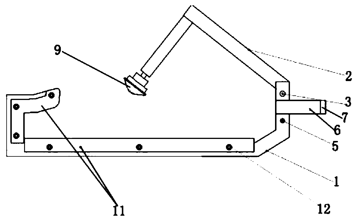
  • Figure 1
    Figure 1
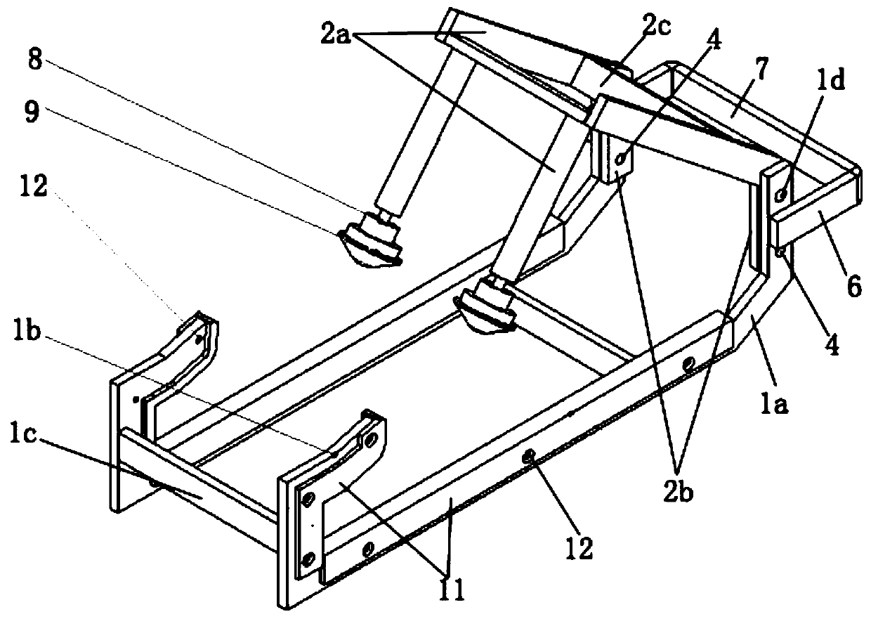
  • Figure 2
    Figure 2
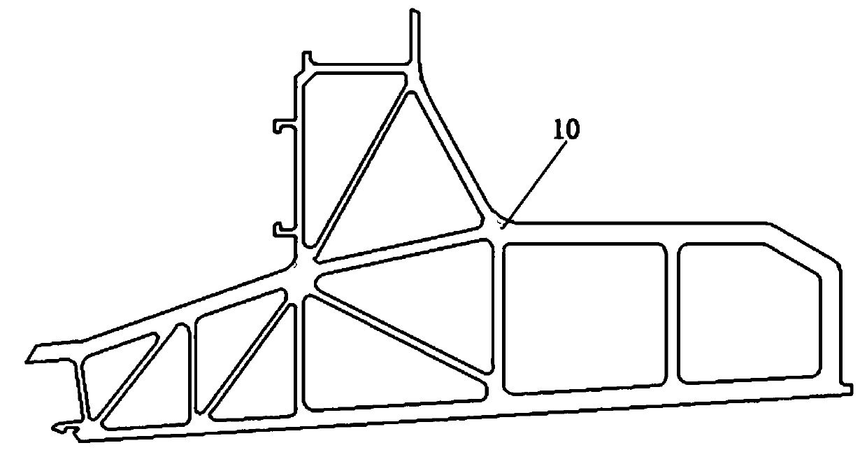
  • Figure 3
    Figure 3
Patent Text Reader

Abstract

The invention discloses a special lifting appliance for railway vehicle floor frame. The special lifting appliance comprises a lifting appliance frame and a lifting appliance buckle, wherein one end of the lifting appliance frame is hinged to one end of the lifting appliance buckle through a rotating shaft and is fixed and limited through a fixed device, and the other end of the lifting applianceframe is in an inner buckle shape; the lifting appliance frame comprises U-shaped beams, inner buckle beams and a first connecting rod, hinge holes for the rotating shaft to penetrate through are formed in one end of each of the U-shaped beams, and the inner buckle beams are arranged at the other ends of the U-shaped beams to form an inner buckle shape; the lifting appliance buckle comprises right-angle beams, connecting beams and second connecting rods, each connecting beam is fixed to one end of the corresponding right-angle beam, and the hinge holes allowing the rotating shaft to penetratethrough are formed in the connecting beams; the lifting appliance frame and the lifting appliance buckle which are hinged with each other are combined with the fixed device for fixing and limiting, sothat the rapid and efficient floor splicing operation can be realized, the operation quality defect caused by improper lifting tools is avoided, the working efficiency is improved, and the problems that in the background art, the efficiency is low during underframe splicing and welding construction, and sectional material collision is caused are solved.
Need to check novelty before this filing date? Find Prior Art

Description

Technical field:

[0001] The invention relates to the field of mechanical hoisting, in particular to a special hoisting tool for rail vehicle floor side beams. Background technique:

[0002] Aluminum alloy car body has the advantages of light weight, corrosion resistance, good appearance flatness and easy to manufacture complex and beautiful curved surface car body, so it is welcomed by urban transportation companies and railway transportation departments all over the world. At present, there are more than 30,000 aluminum alloy urban rail vehicles and railway transport vehicles in operation, and some developing countries are also vigorously developing aluminum alloy car bodies, and have the ability to mass produce aluminum alloy car bodies. With the increasing output, the efficiency of on-site construction needs to be improved. During the production and construction in the workshop, the side beams (such as image 3 ) directly tie the side beams with slings and then drop them...

Examples

Embodiment

[0022] Example: see figure 1 , figure 2 and image 3 , in the figure, 1-spreader frame, 2-spreader buckle, 3-rotating shaft, 4-fixing hole, 5-fixing pin, 6-hanging rod, 7-cross bar, 8-clip ring, 9-ball nylon block, 10-edge beam, 11-U-shaped rubber block, 12-countersunk head screw;

[0023] 1a -U-shaped beam, 1b-inner buckle beam, 1c-first connecting rod, 1d-hinge hole;

[0024] 2a-right angle beam, 2b-connecting beam, 2c-second connecting rod.

[0025] The special spreader for the side beam of the rail vehicle floor includes a spreader frame and a spreader buckle. The spreader frame has a U-shaped structure. One end of the spreader frame is hinged to one end of the spreader buckle through a rotating shaft, and is fixed and limited by a fixing device. The other end of the spreader frame is in the shape of an inner buckle; the spreader frame includes a U-shaped beam, an inner buckle beam and a first connecting rod, one end of the U-shaped beam is provided with a hinged hole...