
Speed limiting device for stacker

A speed limiting device and stacker technology, applied in the direction of lifting device, lifting equipment safety device, etc., can solve the problems of the rapid drop of the lifting platform, the stacker has no speed limit device, and the collision, etc., to avoid collision and easy to use. , the effect of simple structure

Active Publication Date: 2020-07-31
惠安县崇武镇婉云广告设计中心
View PDF8 Cites 0 Cited by
  • Summary
  • Abstract
  • Description
  • Claims
  • Application Information

AI Technical Summary

Problems solved by technology

[0004] The purpose of the present invention is to solve the shortcomings in the prior art that there is no speed-limiting device for the palletizer. When the steel wire rope breaks, the lifting platform will drop rapidly, resulting in a relatively large collision. device

Method used


Image

  • Speed limiting device for stacker
  • Speed limiting device for stacker
  • Speed limiting device for stacker

Examples


Embodiment 1

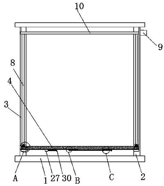
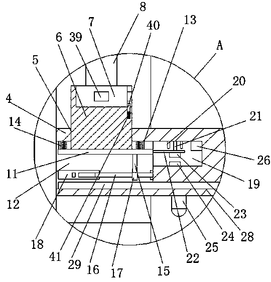
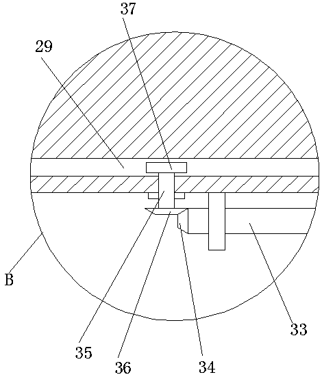
[0029] refer to Figure 1-5 , a speed limiting device for a stacker, comprising a bottom plate 1, two vertical plates 2 are fixedly installed on the top of the bottom plate 1, and a chute 3 is provided on the side where the two vertical plates 2 are close to each other, and the two chute 3 The same lifting platform 4 is slidingly installed inside, and the top of the lifting platform 4 is provided with two sliding holes 5, and a sliding plate 6 is slidingly installed in the two sliding holes 5, and a mounting block 7 is installed on the top of the two sliding plates 6. The tops of each mounting block 7 are fixedly connected with one end of a steel wire rope 8, and the other ends of the two steel wire ropes 8 are fixedly connected with the same drum 10, and both sides of the lifting platform 4 are provided with grooves 12, and the two grooves 12 The connecting plates 11 are all slidably installed, and the tops of the two connecting plates 11 are fixedly connected with the bottom...

Embodiment 2

[0040] refer to Figure 1-5 , a speed limiting device for a stacker, comprising a bottom plate 1, the top of the bottom plate 1 is fixed with two vertical plates 2 by bolts, the sides of the two vertical plates 2 close to each other are provided with chute 3, the two sliding The same lifting platform 4 is slidably installed in the groove 3, and the top of the lifting platform 4 is provided with two sliding holes 5, and a sliding plate 6 is slidably installed in the two sliding holes 5, and a mounting block 7 is installed on the top of the two sliding plates 6 , the tops of the two mounting blocks 7 are fixedly connected with one end of the steel wire rope 8, and the other ends of the two steel wire ropes 8 are fixedly connected with the same drum 10, and both sides of the lifting platform 4 are provided with grooves 12, two grooves Connecting plates 11 are all slidably installed in 12, and the tops of the two connecting plates 11 are fixedly connected with the bottoms of the t...


PUM


Abstract

The invention belongs to the field of speed limiting devices, and particularly relates to a speed limiting device for a stacker. According to the problems that in an existing stacker is provided withno speed limiting device, when steel wire ropes are broken, a lifting platform will descend rapidly, and large colliding is caused, the following scheme is provided, wherein the speed limiting devicecomprises a bottom plate; two vertical plates are fixedly mounted at the top of the bottom plate; sliding grooves are formed in the sides, close to each other, of the two vertical plates; the same lifting platform is mounted in the two sliding grooves in a sliding manner; two siding holes are formed in the top of the lifting platform; sliding plates are mounted in the two sliding holes in a sliding manner; mounting blocks are mounted at the tops of the two sliding plates; one end of a steel wire rope is fixedly connected to the top of each of the two mounting blocks; and the other ends of thetwo steel wire ropes are fixedly connected with the same rotating barrel. According to the speed limiting device, when the steel wire ropes are broken, the descending speed of the lifting platform canbe limited, large colliding is avoided, meanwhile, an alarm can be given, the structure is simple, and use is convenient.

Description

technical field [0001] The invention relates to the technical field of speed limiting devices, in particular to a speed limiting device for a stacker. Background technique [0002] Stacking crane, also known as stacker, refers to a special crane that uses a fork or string rod as a pick-up device to grab, carry and stack in warehouses, workshops, etc., or take and place unit goods from high-rise shelves. storage equipment. [0003] The existing palletizer does not have a speed limiting device. When the wire rope breaks, the lifting platform will drop rapidly, resulting in a large collision. Therefore, we have proposed a speed limiting device for a stacker to solve the above problems. Contents of the invention [0004] The purpose of the present invention is to solve the shortcomings in the prior art that there is no speed-limiting device for the palletizer. When the steel wire rope breaks, the lifting platform will drop rapidly, resulting in a relatively large collision. ...

Claims


Application Information

Patent Timeline
Patent Type & Authority Applications(China)
IPC IPC(8): B66F17/00
CPCB66F17/003
Inventor 王双挺王芳云
Owner 惠安县崇武镇婉云广告设计中心
Learn More