Electric control lock based on shape memory metal wire

A technology of memory metal and electric control locks, which is applied in the field of electric control locks, can solve problems such as difficult access to unlock strokes, large telescopic strokes, and large stroke loss.

Pending Publication Date: 2020-07-31
SENSOR ELECTRONICS CO LTD
View PDF0 Cites 4 Cited by
  • Summary
  • Abstract
  • Description
  • Claims
  • Application Information

AI Technical Summary

Problems solved by technology

Although the shape memory wire is used to replace the electromagnet part in this lock, it does not change its disadvantage of being too large. In addition, this lock has very low requirements for the driving stroke of the shape memory wire and is very sensitive to displacement changes. Therefore, , the application of shape memory metal wire in this structure is relatively successful
[0004] For this lock with the patent number 2016203043592, the electromagnet is replaced by a shape memory wire. The effect of the shape memory wire directly connected to the lock tongue to drive the lock tongue is relatively poor, because the lock tongue of this lock is telescopic. , the telescopic stroke is relatively large
The shrinkage rate of the shape memory metal wire is limited, and it is difficult to obtain enough travel to realize the unlocking when the shape memory wire is directly applied to the lock tongue
If an ideal stroke is forcibly obtained by increasing the input power, it is easy to make the shape-memory metal wire thinner and the slack higher, resulting in greater stroke loss, and a smaller driving stroke of the lock bolt. It will become more and more difficult to open the lock or not at all, and it is even easy to break the shape memory wire

Method used


Image

  • Electric control lock based on shape memory metal wire
  • Electric control lock based on shape memory metal wire
  • Electric control lock based on shape memory metal wire

Examples


Embodiment Construction

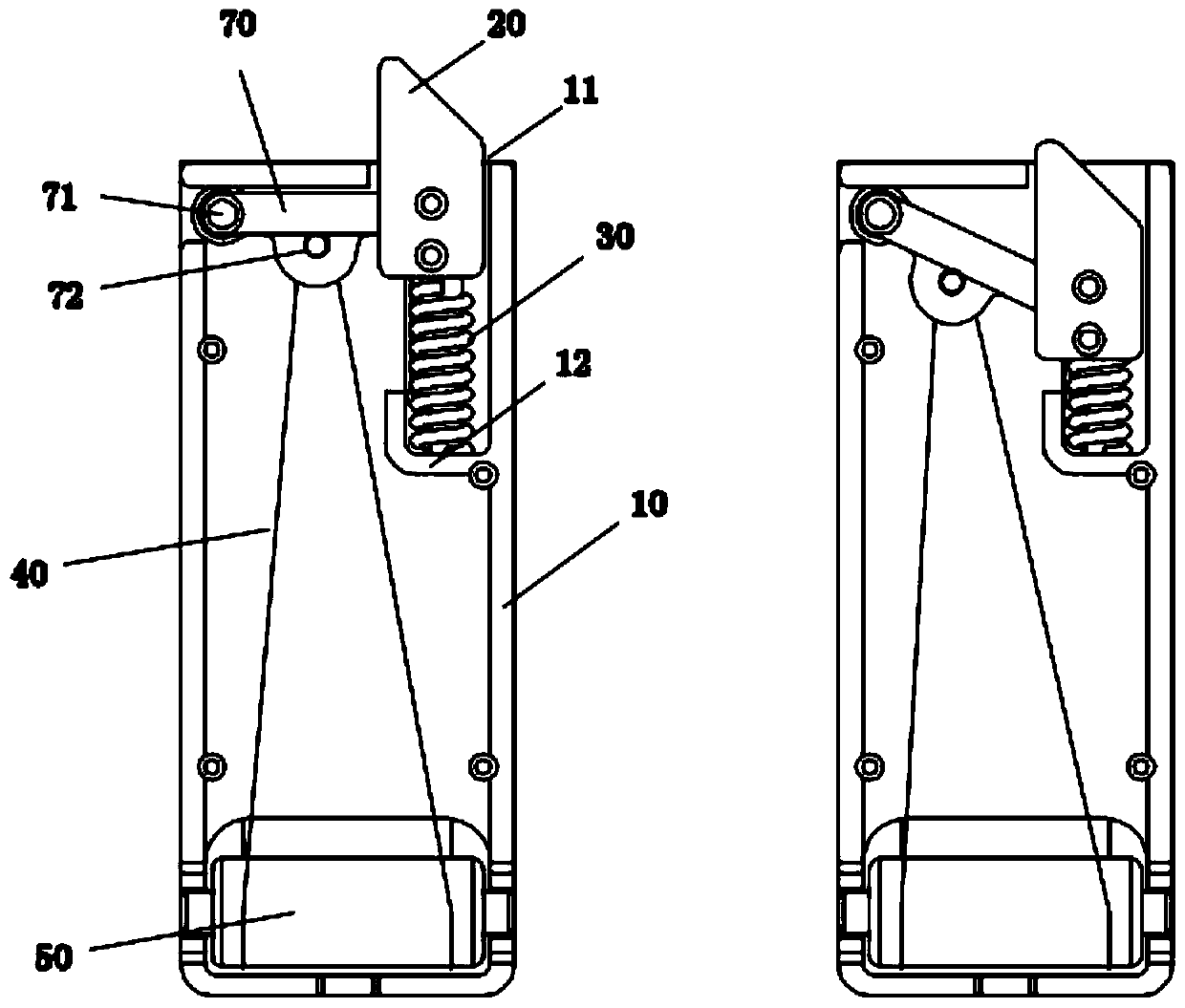
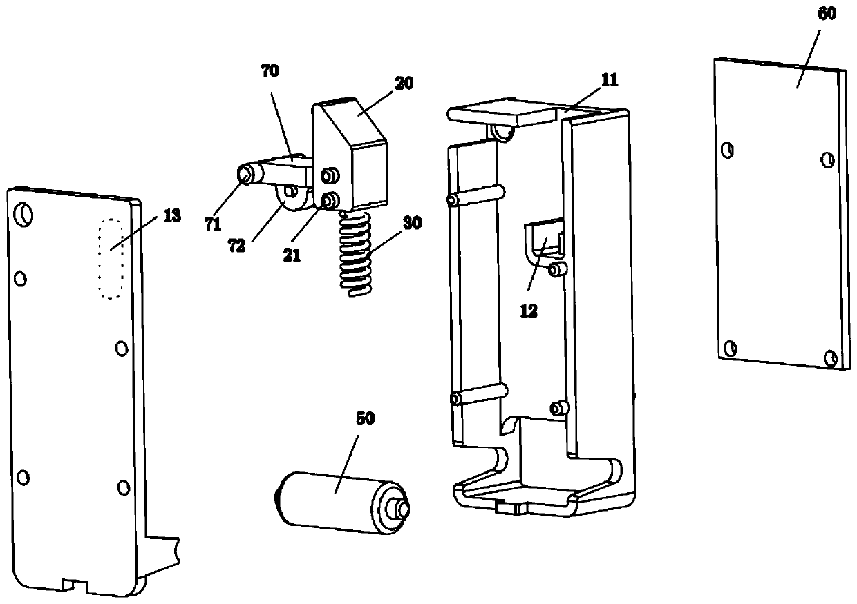
[0017] In order to make the technical solutions and advantages of the present invention clearer, the implementation manners of the present invention will be clearly and completely described below in conjunction with the accompanying drawings. Apparently, the described embodiments are some, not all, embodiments of the present invention. Based on the described embodiments, all other embodiments obtained by persons of ordinary skill in the art without creative efforts shall fall within the protection scope of the present invention.

[0018] In the present invention, it is to be understood that the terms "upper", "middle", "lower", "top", "bottom", "end", "left", "right", "vertical", "horizontal" , "vertical", "horizontal", "inner", "outer", "side" and other indicated orientations or positional relationships are based on the orientations or positional relationships shown in the drawings, and their orientations or positional relationships are relative, only It is for the convenien...


PUM


Abstract

The invention discloses an electric control lock based on a shape memory metal wire. The electric control lock based on the shape memory metal wire includes a shell, a lock tongue telescoping in the shell, a reset piece connected to the end of the lock tongue, and the shape memory metal wire used for driving the electric control lock to unlock; wherein a stroke enlargement piece is arranged between the lock tongue and the shape memory metal wire; and when the shape memory metal wire drives the stroke enlargement piece to generate a displacement, the stroke enlargement piece drives the lock tongue to generate an enlarged displacement. The stroke enlargement piece is not limited to a lever, a gear, and a cam. According to the scheme, the driving force of the shape memory metal wire does notdirectly act on the lock tongue, but acts on the stroke enlargement piece; the stroke enlargement piece obtains a smaller displacement, so that the lock tongue obtains a larger displacement; and therefore, the problem described in the description is solved, and the lock also retains the advantages of being compact.

Description

technical field [0001] The invention relates to the field of locks, in particular to an electric control lock based on a shape memory wire. Background technique [0002] Patent No. 2018211427856, "An Electromagnetic Lock", is widely used in the market, such as express boxes and unmanned vending machines. This lock body is relatively large and takes up a lot of space. Patent No. 2016203043592 published "Simple Electromagnetic Lock" This lock is more compact, only about one-eighth of the lock in 2018211427856, with a simpler structure, fewer parts, lower cost, and more conducive to the miniaturization of equipment and save equipment space. Both of these locks use the principle of electromagnetism. The electromagnet is the core component of this type of lock. The electromagnet is generally made of copper wire and requires a long copper wire. Therefore, the electromagnet occupies a large part of the lock. main cost. Another type of metal, such as titanium wire, nickel-titaniu...

Claims


Application Information

Patent Timeline
Patent Type & Authority Applications(China)
IPC IPC(8): E05B51/00E05B15/00E05B15/10E05B9/00
CPCE05B51/005E05B15/00E05B15/101E05B9/00E05B47/026E05B2047/002
Inventor 万信超袁亚庭
Owner SENSOR ELECTRONICS CO LTD
Why Eureka
Try Eureka