
A self-priming inverted bucket trap
A trap, self-priming technology, applied in steam traps, mechanical equipment, etc., can solve problems such as unfavorable energy saving and emission reduction, and achieve the effect of preventing leakage and waste.
- Summary
- Abstract
- Description
- Claims
- Application Information
AI Technical Summary
Problems solved by technology
Method used
Image

Examples
Embodiment Construction
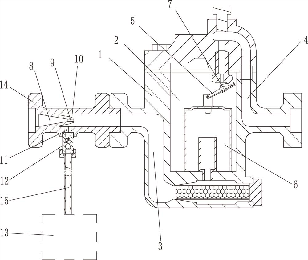
[0011] The present invention will be described in further detail below in conjunction with accompanying drawing and specific embodiment: see figure 1 , a self-priming inverted bucket trap, comprising a valve body 1, a gas-liquid separation chamber 2, a steam inlet passage 3 and a liquid outlet passage 4 are arranged on the valve body 1, and the steam inlet passage 3 is separated from the gas-liquid separation chamber 2 The bottom extends, and the liquid outlet channel 4 is located at the top of the gas-liquid separation chamber 2. The bottom of the liquid outlet channel 4 is provided with a rotating arm 5. The rotating arm 5 is rotatably connected with an inverted bucket 6. The inverted bucket 6 is covered on the steam inlet channel 3. The arm 5 is provided with a spool 7, and the inverted bucket 6 is raised and lowered to make the spool 7 block or open the outlet channel 4. Along the steam flow direction, a conical guide section 8, an injection area 9, and a vacuum chamber 10 ...
PUM
 Abstract
Description
Claims
Application Information