Power lithium battery heat dissipation mechanism

A technology of heat dissipation mechanism and lithium battery, which is applied in the direction of secondary battery, battery pack parts, battery and environment isolation, etc., can solve the problems of lithium battery shaking, poor heat dissipation effect, etc., so as to improve the safety of use, good heat dissipation effect, The effect of ensuring the safety of personnel

Inactive Publication Date: 2020-07-31
安徽西尔艾智能科技有限公司
View PDF0 Cites 1 Cited by
  • Summary
  • Abstract
  • Description
  • Claims
  • Application Information

AI Technical Summary

Problems solved by technology

[0004] The purpose of the present invention is to provide a power lithium battery heat dissipation mechanism, through the cooperation of the heat sink and the ventilation fan, the inner cavity of the shell can be ventilated, so as to avoid excessive heat in the inner cavity and reduce the service life of the lithium battery body; by setting the water tank, Input cold water into the water tank, connect the first water pump through the first water pipe to input cold water to the cooling water plate for cooling treatment, when the cold water absorbs heat and heats up, the second water pump can be connected to the second water pipe to communicate with the water tank for cold water circulation, and through The electric push rod pushes the lithium battery holder to move up and down. When the lithium battery body is hot, put the lithium battery closer to the heat dissipation water plate, which can quickly cool down and the heat dissipation effect is better; to solve the heat dissipation effect of the ordinary power lithium battery proposed in the above background technology It is not good and it is easy to cause the lithium battery to shake in the inner cavity of the shell when moving

Method used


Image

  • Power lithium battery heat dissipation mechanism
  • Power lithium battery heat dissipation mechanism
  • Power lithium battery heat dissipation mechanism

Examples


Embodiment 1

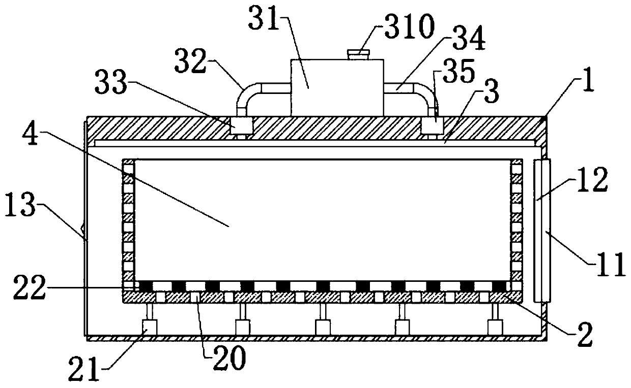
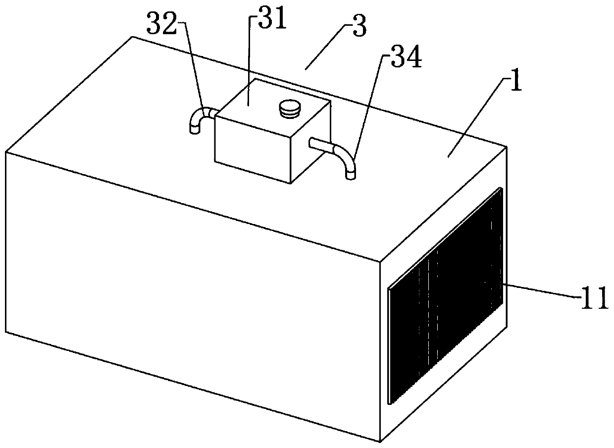
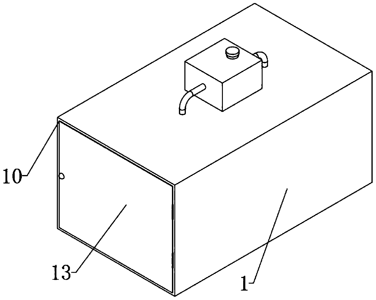
[0030] A power lithium battery heat dissipation mechanism, in order to solve the problem that the heat dissipation effect of ordinary power lithium batteries is not good and the lithium battery is easily caused to shake in the inner cavity of the shell when moving, as a preferred embodiment, as figure 1 , figure 2 and image 3 As shown, including the shell 1, the inner cavity of the shell 1 is provided with a lithium battery holder 2, and the lithium battery holder 2 is provided with a vent hole 20, which is convenient for ventilation and heat dissipation. The bottom of the inner cavity of the lithium battery holder 2 is provided with a spring buffer 22. The top of the device 22 is provided with a lithium battery body 4, the lithium battery body 4 is located at the top of a plurality of spring buffers 22, the lithium battery body 4 is located in the inner cavity of the lithium battery holder 2, and the spring buffer 22 can prevent the lithium battery body from being buffered ...


PUM


Abstract

The invention relates to the technical field of lithium batteries, specifically to a power lithium battery heat dissipation mechanism, which comprises a shell, wherein a lithium battery holder is arranged in the inner cavity of the shell, an air permeable hole is formed in the lithium battery holder, an electric push rod is arranged at the bottom of the lithium battery holder, a spring buffer device is arranged at the bottom of the inner cavity of the lithium battery holder, a lithium battery body is arranged at the top of the spring buffer device, the lithium battery body is positioned in theinner cavity of the lithium battery holder, a heat dissipation water plate is arranged at the top of the inner cavity of the shell, the water drainage pipe of a first water pump communicates with oneend of the top of the heat dissipation water plate, the water suction pipe of the first water pump communicates with a first water pipe, the first water pipe is communicated with a water tank, the top of the other end of the heat dissipation water plate communicates with the water suction pipe of a second water pump, the water drainage pipe of a second water pump communicates with a second waterpipe, the second water pipe is communicated with the water tank, a ventilating fan is arranged on the side face of the inner cavity of the shell, cooling fins are arranged at the exhaust end of the ventilating fan, and the cooling fins are embedded in the side face of the shell. According to the invention, the heat dissipation effect is good, and the situation that the lithium battery body shakesand is damaged in the shell can be avoided.

Description

technical field [0001] The invention relates to the technical field of lithium batteries, in particular to a power lithium battery heat dissipation mechanism. Background technique [0002] Lithium battery is a type of battery that uses lithium metal or lithium alloy as the negative electrode material and uses a non-aqueous electrolyte solution. In 1912, the lithium metal battery was first proposed and studied by Gilbert N. Lewis. In the 1970s, M.S.Whittingham proposed and began to study lithium-ion batteries. Due to the very active chemical properties of lithium metal, the processing, storage and use of lithium metal have very high environmental requirements. Therefore, lithium batteries have not been used for a long time. With the development of science and technology, lithium batteries have become the mainstream now. [0003] Power lithium-ion battery refers to a lithium-ion battery with a capacity of more than 3AH. At present, it generally refers to a lithium-ion batt...

Claims


Application Information

Patent Timeline
Patent Type & Authority Applications(China)
IPC IPC(8): H01M2/10H01M10/613H01M10/625H01M10/6551H01M10/6554H01M10/6563H01M10/6568H01M50/249
CPCH01M10/613H01M10/625H01M10/6568H01M10/6563H01M10/6554H01M10/6551H01M50/20H01M50/24Y02E60/10
Inventor 王翠翠周俊峰王凯何赛丹崔文鹤
Owner 安徽西尔艾智能科技有限公司
Why Eureka
Try Eureka