Full-automatic cutting component for PVC pipeline machining

A cutting member, fully automatic technology, applied in metal processing and other directions, can solve the problems of low cutting efficiency, low precision, poor flatness of the end face, etc., and achieve the effect of convenient operation, high degree of automation and high cutting precision.

Inactive Publication Date: 2020-08-04
陈满平
View PDF12 Cites 1 Cited by
  • Summary
  • Abstract
  • Description
  • Claims
  • Application Information

AI Technical Summary

Problems solved by technology

[0002] Ordinary PVC pipe cutting machines mainly include motors and cutting discs driven by motors, which are divided into small hand-held cutting machines and large floor-standing cutting machines. In the process of cutting pipe fittings by ordinary cutting, there are the following defects. First, it cannot Firmly clamping and clamping the pipe fittings, the pipe fittings are prone to offset during cutting, resulting in poor flatness and low precision of the cutting end surface; second, the pipe fittings cannot be automatically fed, which is not conducive to continuous fixed-length cutting, resulting in cutting The efficiency is low, it is necessary to provide a fully automatic pipe fitting cutting member with ingenious structure, simple principle, convenient operation, high degree of automation, and high cutting precision.

Method used


Image

  • Full-automatic cutting component for PVC pipeline machining
  • Full-automatic cutting component for PVC pipeline machining
  • Full-automatic cutting component for PVC pipeline machining

Examples


Embodiment Construction

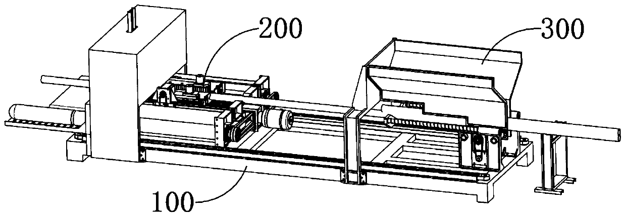
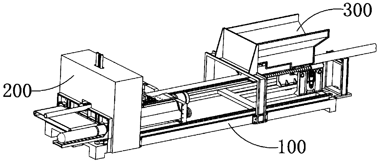
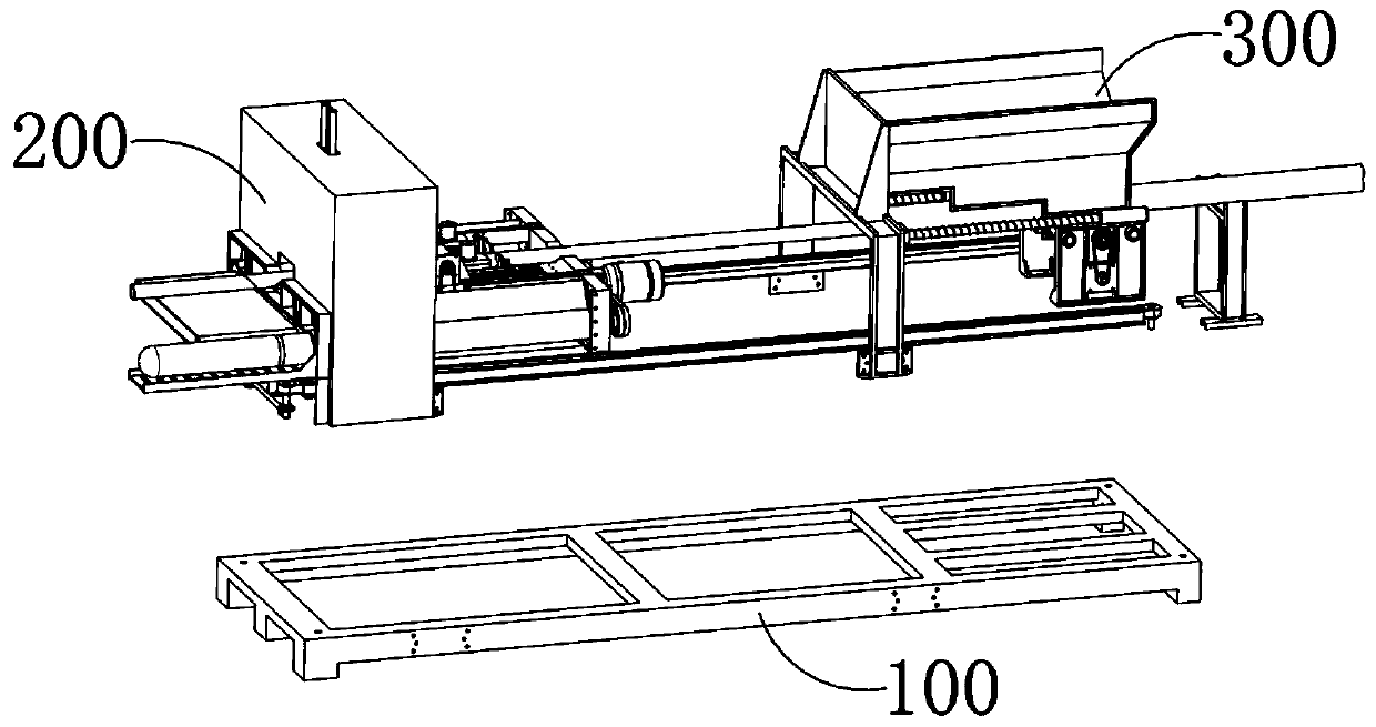
[0056] see Figure 1-36 , a fully automatic fixed-length cutting machine for pipe fittings, which includes a rectangular base frame 100, a cutting part 200 and a feeding part 300, the cutting part 200 is close to one end of the base frame 100 along the length direction, and the feeding part 300 is close to the bottom frame 100 along the At the other end in the length direction, the cutting unit 200 includes a clamping mechanism 210, a cutting mechanism 240, a slag discharge mechanism 250, a material discharge mechanism 260, and a sliding drive mechanism 270. The clamping mechanism 210 is used for guiding, clamping and clamping the pipe fittings , the cutting mechanism 240 cuts the clamped pipe fittings from top to bottom, the slag discharge mechanism 250 is used to collect and remove the debris that falls from the pipe fittings cut by the cutting mechanism 240, and the discharge mechanism 260 is used to cut off the pipe fittings from the cutting mechanism 240. Afterwards, the ...


PUM


Abstract

The invention provides a full-automatic cutting component for PVC pipeline machining. The full-automatic cutting component for PVC pipeline machining comprises a clamping mechanism and a cutting mechanism, the clamping mechanism comprises long-strip-shaped mounting frames parallel to a length direction of a bottom frame, guide columns are fixedly arranged between the two mounting frames, and sliding plates are connected to the guide columns in a sleeving mode and can slide in axial directions of the guide columns; rectangular floating frames are movably arranged on inner sides of the sliding plates, first floating rods are fixedly arranged on the end faces, away from each other, of the floating frames, the first floating rods penetrate through the sliding plates, and the first floating rods and the sliding plates are in sliding guide fit in a width direction of a bottom frame; each first floating rod is sleeved with floating springs, and a driving roller, a driven roller and a transition roller are vertically arranged in an axial direction are rotationally arranged on each floating frame, a clamping belt which is wound between the driving roller and the driven roller and forms a closed circulation loop is arranged between the driving roller and the driven roller, a circulating driving motor is fixedly arranged on an upper end face of each floating frame, and an output shaft ofeach circulating driving motor is vertically downward in the axial direction and is connected with a rotating shaft of the driving roller.

Description

technical field [0001] The invention relates to a cutting machine, in particular to a fully automatic cutting component for PVC pipe processing. Background technique [0002] Ordinary PVC pipe cutting machines mainly include motors and cutting discs driven by motors, which are divided into small hand-held cutting machines and large floor-standing cutting machines. In the process of cutting pipe fittings by ordinary cutting, there are the following defects. First, it cannot Firmly clamping and clamping the pipe fittings, the pipe fittings are prone to offset during cutting, resulting in poor flatness and low precision of the cutting end surface; second, the pipe fittings cannot be automatically fed, which is not conducive to continuous fixed-length cutting, resulting in cutting The efficiency is low, so it is necessary to provide a fully automatic pipe fitting cutting member with ingenious structure, simple principle, convenient operation, high degree of automation, and high ...

Claims


Application Information

Patent Timeline
Patent Type & Authority Applications(China)
IPC IPC(8): B26D1/16B26D5/08B26D5/06B26D7/02B26D7/06B26D7/18B26D7/00
CPCB26D1/16B26D5/06B26D5/086B26D7/00B26D7/02B26D7/0625B26D7/18B26D2007/013
Inventor 陈满平
Owner 陈满平
Why Eureka
Try Eureka