

LCD device
A liquid crystal display, liquid crystal panel technology, applied in static indicators, instruments, instrument parts and other directions, can solve the problems of increased module cost, increased cost of circuit boards, low prices of metal shrapnel and metal conductive cloth, etc., and achieves good grounding. effect, stable clamping, improve the effect of electromagnetic wave interference
- Summary
- Abstract
- Description
- Claims
- Application Information
AI Technical Summary
Problems solved by technology
Method used
Image

Examples
Embodiment Construction
[0054] The invention discloses a liquid crystal display, which can make a printed circuit board obtain a good grounding effect without using additional parts, and effectively improve the problem of electromagnetic wave interference. In order to make the description of the present invention more detailed and complete, refer to the following description and cooperate with Fig. 1 to Figure 7B icon of the .
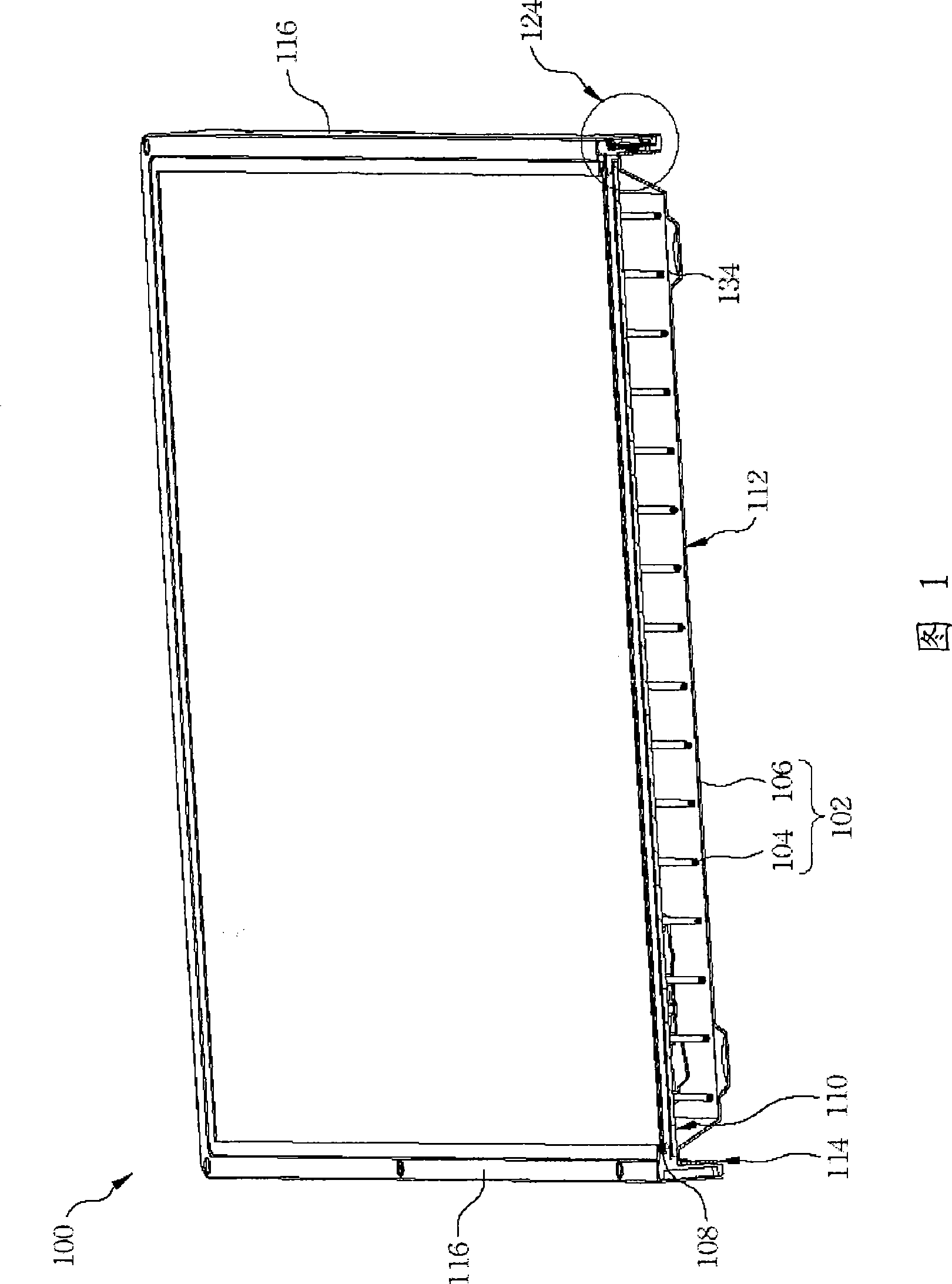
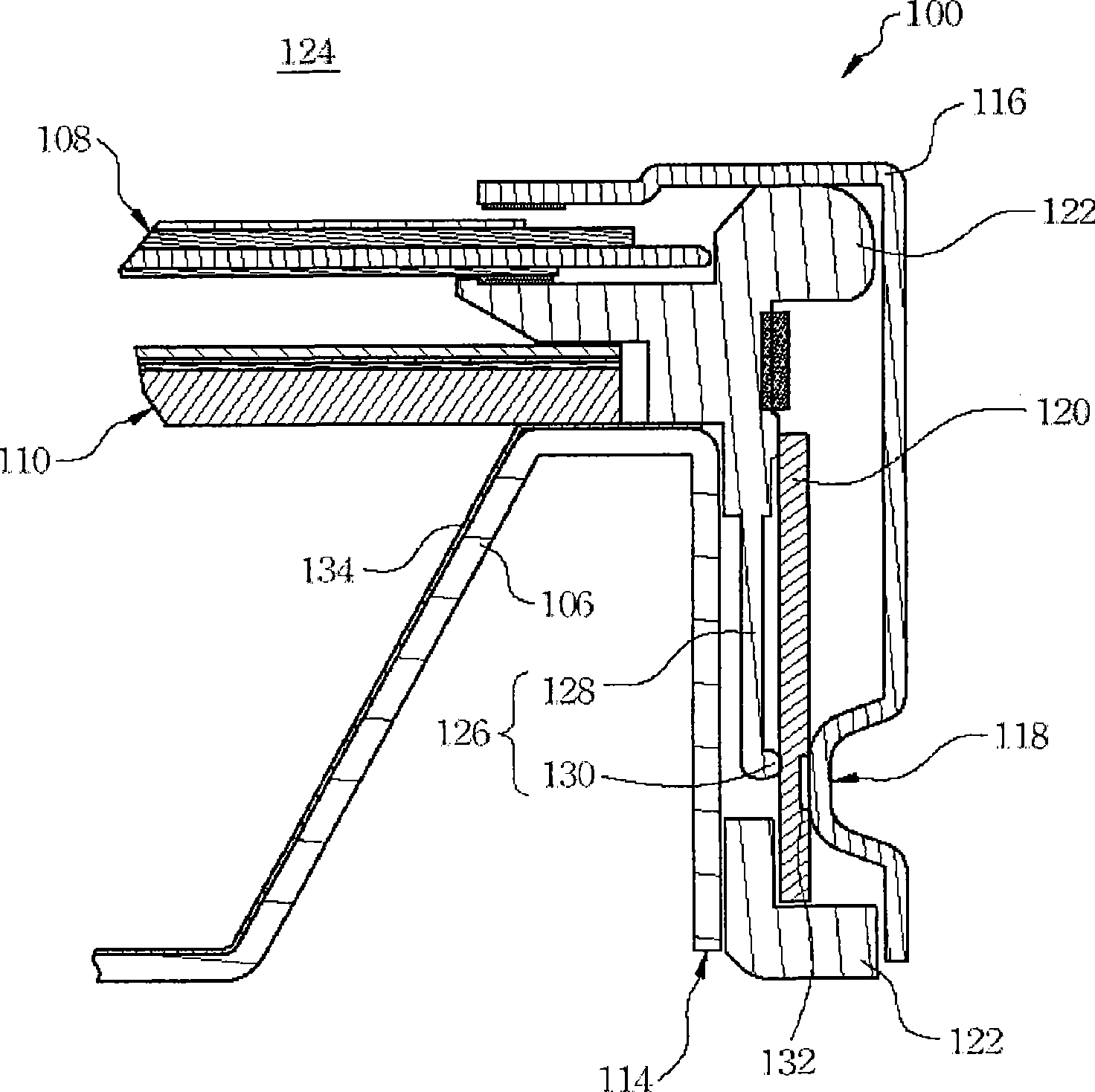
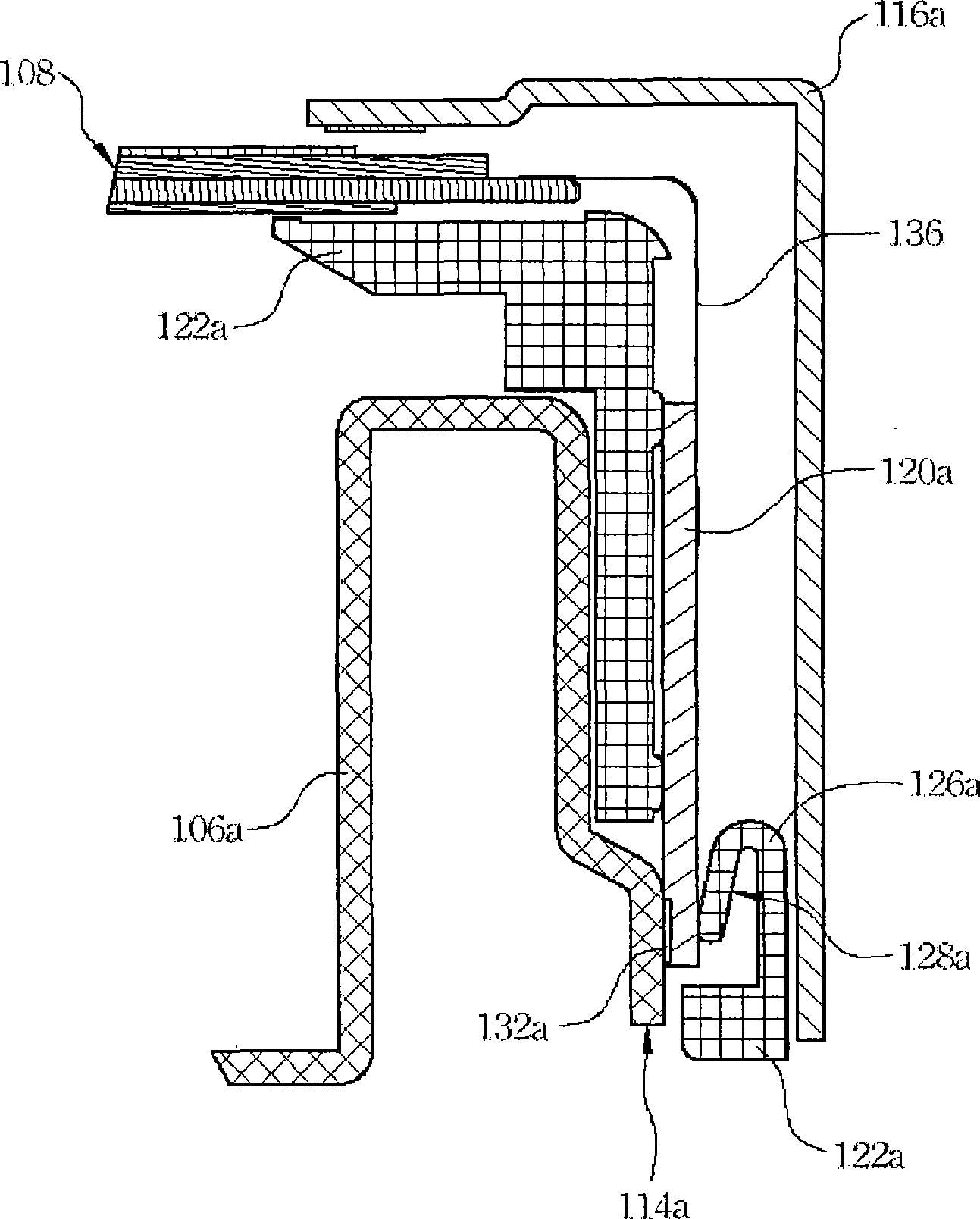
[0055] Please refer to Figure 1 with figure 2 , wherein FIG. 1 is a three-dimensional cross-sectional view illustrating a liquid crystal display according to a preferred embodiment of the present invention, and figure 2 Then it is an enlarged cross-sectional view showing the peripheral portion of the liquid crystal display shown in FIG. 1 . The liquid crystal display 100 mainly includes a backlight module 102 , a liquid crystal panel module 108 , a front frame 116 and a printed circuit board 120 . The backlight module 102 mainly includes a backplane 106 , a light source g...
PUM
 Abstract
Description
Claims
Application Information