Supercharge Your Innovation With Domain-Expert AI Agents!

External combustion engine for reducing mechanical loss energy by using characteristics of thermal expansion and cold shrinkage

A technology of thermal expansion and contraction, mechanical loss, applied in mechanical equipment, machines/engines, engine components, etc., it can solve problems such as reducing the working effect of mechanical energy, increasing thermal energy, etc., to achieve the effect of overcoming mechanical frictional resistance

Inactive Publication Date: 2020-08-04
陈兆真
View PDF0 Cites 0 Cited by
  • Summary
  • Abstract
  • Description
  • Claims
  • Application Information

AI Technical Summary

Problems solved by technology

[0003] With the continuous development of industrial technology, external combustion engines have been used in various fields, but the disadvantage of existing external combustion engines is that while heat energy provides mechanical motion, part of the capacity is used to overcome various problems when mechanical equipment moves. The friction between parts and the resistance generated by friction will reduce the working effect of mechanical energy, and the existing technology adopts the method of artificially overcoming or increasing heat energy, which cannot fundamentally solve the problem. The external combustion engine with mechanical loss came into being

Method used


Image

  • External combustion engine for reducing mechanical loss energy by using characteristics of thermal expansion and cold shrinkage
  • External combustion engine for reducing mechanical loss energy by using characteristics of thermal expansion and cold shrinkage
  • External combustion engine for reducing mechanical loss energy by using characteristics of thermal expansion and cold shrinkage

Examples


Embodiment Construction

[0025] The following will clearly and completely describe the technical solutions in the embodiments of the present invention with reference to the accompanying drawings in the embodiments of the present invention. Obviously, the described embodiments are only some, not all, embodiments of the present invention. Based on the embodiments of the present invention, all other embodiments obtained by persons of ordinary skill in the art without making creative efforts belong to the protection scope of the present invention.

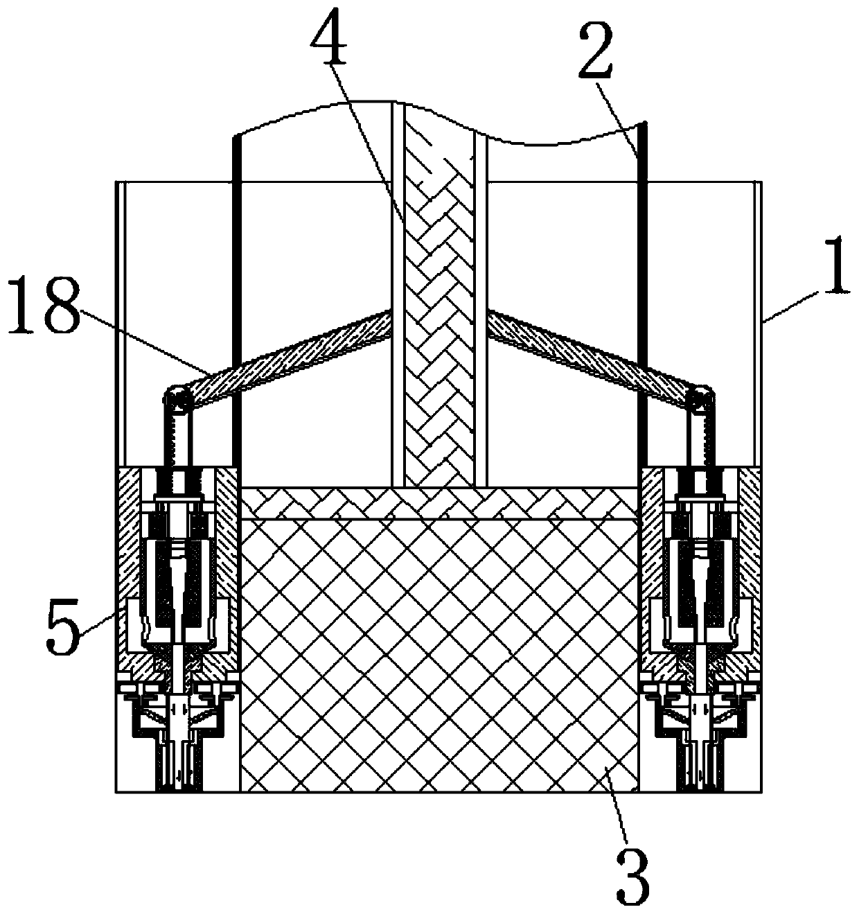
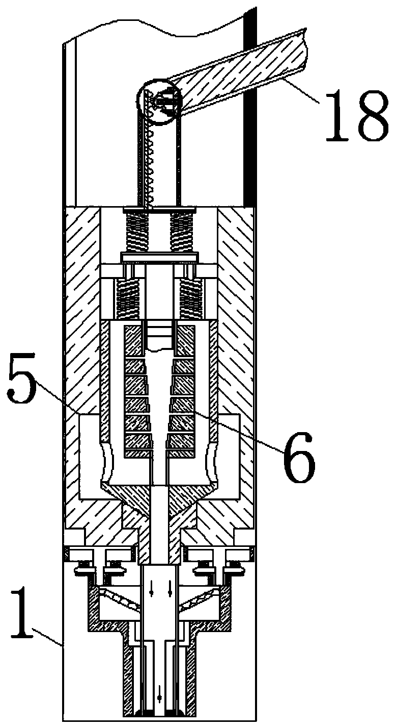
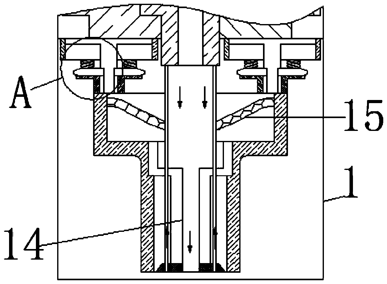
[0026] see Figure 1-8 , an external combustion engine that utilizes thermal expansion and contraction characteristics to reduce mechanical energy loss, including a housing 1, the bottom of the housing 1 is fixedly connected with a gas pipeline, and the gas in the gas pipeline is high-temperature steam, also known as "water vapor" , According to pressure and temperature, various types of steam are classified into: saturated steam, superheated steam. The main ...


PUM


Abstract

The invention relates to the technical field of reducing mechanical friction loss energy of external combustion engines, and discloses an external combustion engine for reducing mechanical loss energyby using the characteristics of thermal expansion and cold shrinkage. The external combustion engine comprises a shell, a sliding groove is formed in the shell, the surface of the sliding groove is slidably connected with a piston, the surface of the piston is fixedly connected with a shaft rod, energy storage grooves are formed in the portions, on the two sides of the piston, in the shell respectively, storage grooves are fixedly connected in the energy storage grooves, and diversion layers are formed in the surfaces of the storage grooves. Spring plates are movably connected with the tops of the storage grooves, push rods are movably connected with the surfaces of the spring plates, toothed plates are movably connected in the push rods, gears are movably connected with the surfaces of the toothed plates, connecting plates are movably connected with the surfaces of the gears, and twisting rods are fixedly connected with the surfaces of the connecting plates. The deflecting directionof booster rods is identical to the moving direction of the shaft rod, therefore, the force of the booster rods can neutralize the friction resistance generated during mechanical movement, and the effect of overcoming the friction resistance by using a thermal-shrinkage and cold-expansion material is achieved.

Description

technical field [0001] The invention relates to the technical field of reducing mechanical frictional energy loss of an external combustion engine, in particular to an external combustion engine that utilizes thermal expansion and contraction characteristics to reduce mechanical energy loss. Background technique [0002] The external combustion engine uses fuel combustion to heat the circulating working medium, such as a steam engine that transports the high-temperature and high-pressure water vapor generated by heating the water in the boiler to the inside of the machine to convert heat energy into mechanical energy. The typical work is the Stirling engine. The Stirling engine was invented by Stirling in 1816, which can avoid the problems of cylinder shock and insufficient combustion caused by internal combustion engines. [0003] With the continuous development of industrial technology, external combustion engines have been used in various fields, but the disadvantage of e...

Claims


Application Information

Patent Timeline
IPC IPC(8): F01B29/12F01B31/08F01B31/10
CPCF01B29/12F01B31/08F01B31/10
Inventor 陈兆真
Owner 陈兆真
Features
  • R&D
  • Intellectual Property
  • Life Sciences
  • Materials
  • Tech Scout
  • Unparalleled Data Quality
  • Higher Quality Content
  • 60% Fewer Hallucinations
Learn More