Pressure transmitter with adjustable pressure sensor
A pressure sensor and transmitter technology, applied in the direction of measuring fluid pressure, instruments, measuring devices, etc., can solve the problems of inconvenient disassembly and assembly, poor sensor output accuracy, inability to adjust the position of the pressure sensor, etc., to achieve convenient adjustment and eliminate output. Effects of Precision Errors
- Summary
- Abstract
- Description
- Claims
- Application Information
AI Technical Summary
Problems solved by technology
Method used
Image
Examples
Embodiment 1
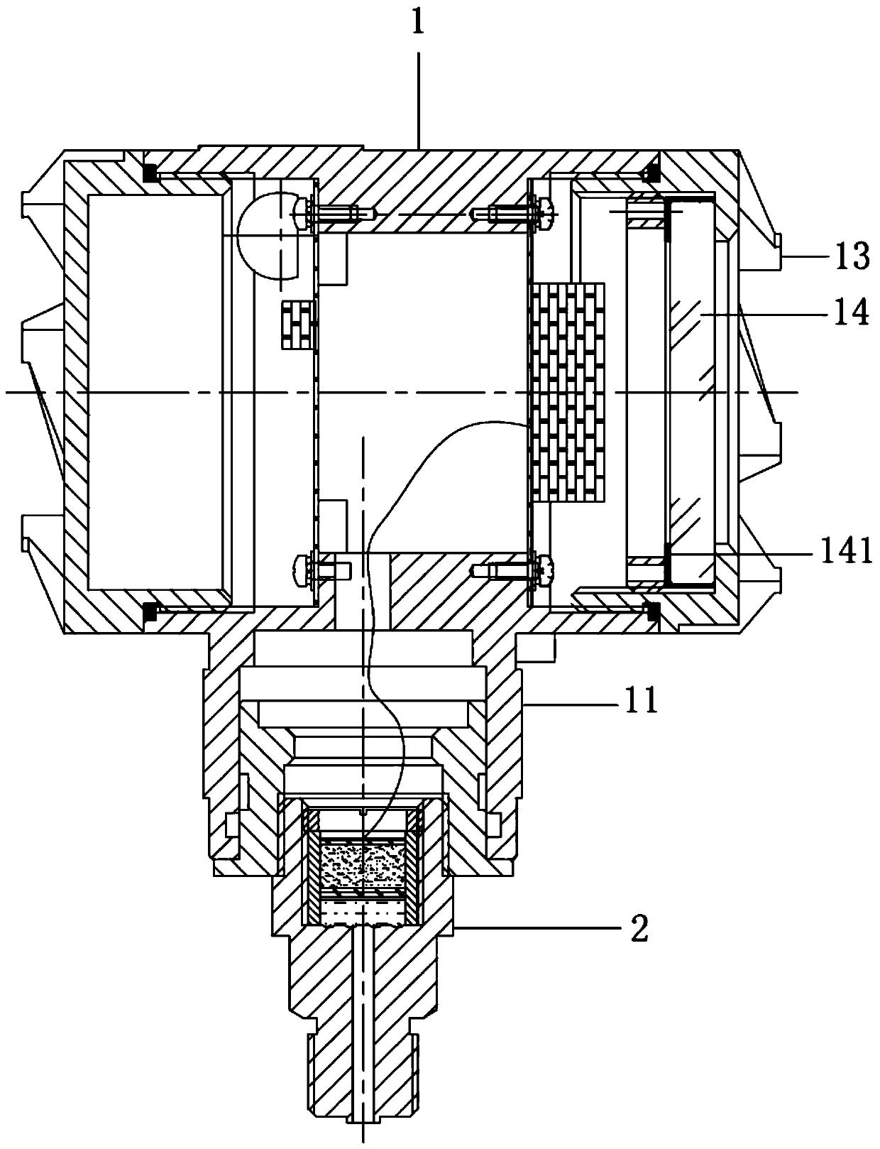
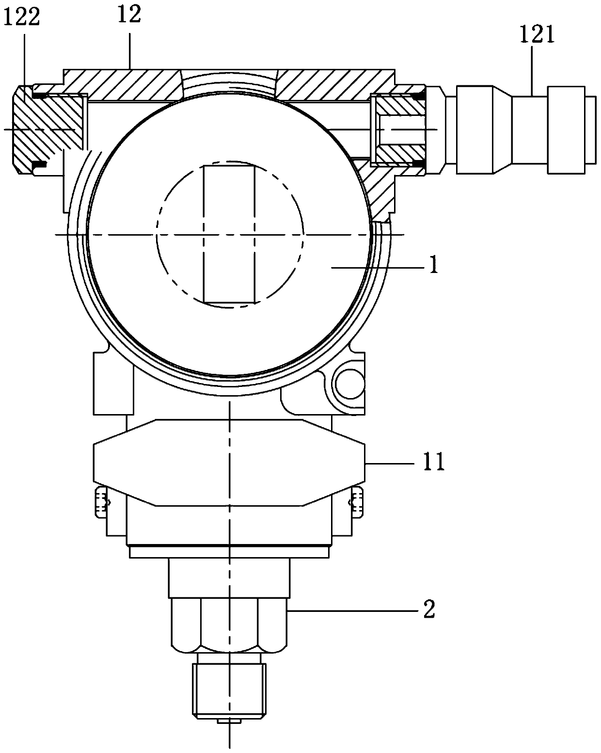
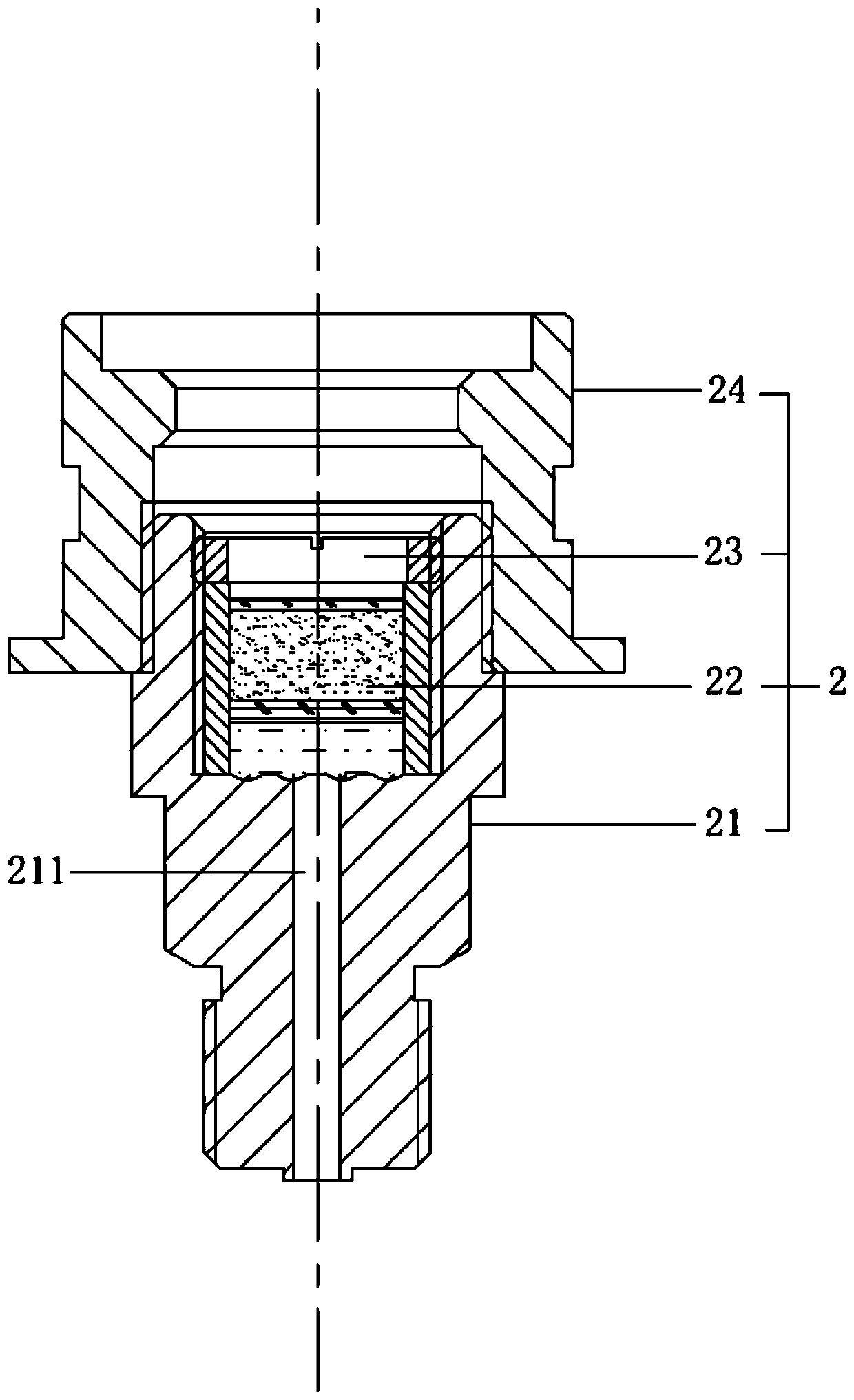
[0021] see Figure 1 to Figure 3 , the figure shows a pressure transmitter with an adjustable pressure sensor provided by Embodiment 1 of the present invention, including a gauge head 1 and a pressure joint 2, a joint pipe 11 is provided at the bottom of the gauge head 1, and the pressure joint 2 includes a connecting sleeve 21. Pressure sensor 22, sensor pressure sleeve 23 and transition sleeve 24, a cavity and a fluid pipeline 211 are arranged in the connection sleeve 21, a pressure sensor 22 is arranged in the cavity, the sensor pressure sleeve 23 is threaded in the cavity, and the fluid pipeline 211 is automatically The end of the connecting sleeve 21 extends to the cavity, the connecting sleeve 21 is screwed into the transition sleeve 24 , and the transition sleeve 24 is fixedly installed in the joint pipe 11 .
[0022] Specifically, see Figure 1 to Figure 3 , The transition sleeve 24 is bonded in the joint pipe 11.
[0023] The present invention provides a pressure tr...
Embodiment 2
[0026] see Figure 1 to Figure 3 , the figure shows a pressure transmitter with an adjustable pressure sensor provided by Embodiment 2 of the present invention. On the basis of the above embodiment, this embodiment further makes the following technical solutions as improvements: connecting sleeve When the 21 is fixedly installed in the transition sleeve 24, the surface of the thread is provided with epoxy resin glue.
[0027] The connection sleeve and the transition sleeve are fixed by the explosion-proof thread joint surface. When the connection sleeve is threaded into the transition sleeve, epoxy resin glue is applied to the thread, which can not only ensure the tightness of the installation, but also play a sealing effect to avoid affect the pressure sensor measurement.
Embodiment 3
[0029] see Figure 1 to Figure 3 , the figure shows a pressure transmitter with an adjustable pressure sensor provided by Embodiment 3 of the present invention. On the basis of the above embodiments, this embodiment further makes the following technical solutions as improvements: gauge head 1 is provided with a fixed cover 12, one end of the fixed cover 12 is provided with a cable connector 121, and the other end is provided with a plug 122; the cable connector 121 is a clamping joint.
[0030] The cable connector on the fixed cover on the meter head is connected to the explosion-proof cable, and the clamping connector ensures the tightness of the installation.
PUM
 Abstract
Description
Claims
Application Information
 - R&D
- Intellectual Property
- Life Sciences
- Materials
- Tech Scout
- Unparalleled Data Quality
- Higher Quality Content
- 60% Fewer Hallucinations
Browse by: Latest US Patents, China's latest patents, Technical Efficacy Thesaurus, Application Domain, Technology Topic, Popular Technical Reports.
© 2025 PatSnap. All rights reserved.Legal|Privacy policy|Modern Slavery Act Transparency Statement|Sitemap|About US| Contact US: help@patsnap.com


