
Touch display device and laminating method thereof

A technology for a touch display device and a display panel, which is applied in the directions of instruments, electrical digital data processing, and data processing input/output processes, etc., can solve the problem that the overall sealing structure occupies a large area and is difficult to apply to the touch display device. It can reduce the cost of materials, simplify the setting, and reduce the occupied area.

Active Publication Date: 2020-08-04
CORETRONIC DISPLAY SUZHOU CO LTD
View PDF1 Cites 2 Cited by
  • Summary
  • Abstract
  • Description
  • Claims
  • Application Information

AI Technical Summary

Problems solved by technology

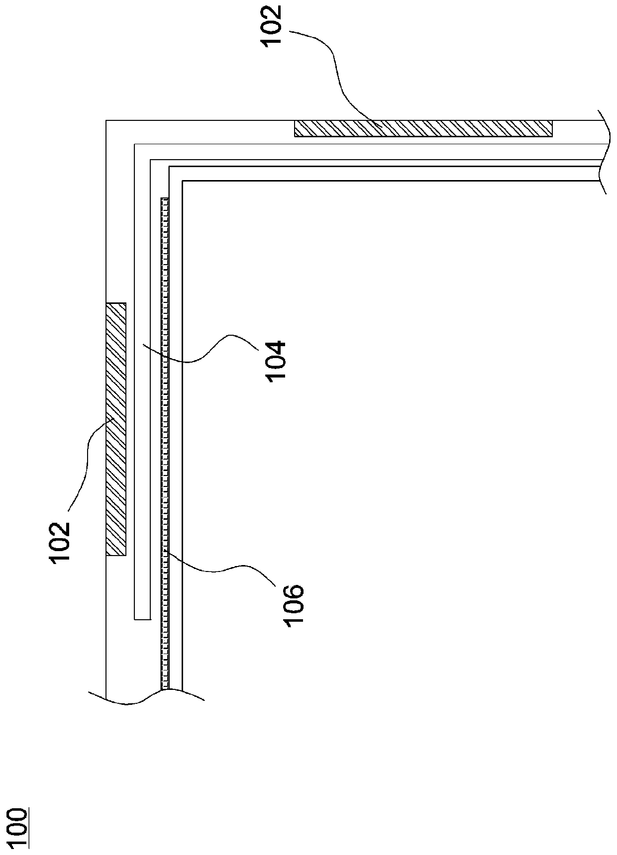
However, in a conventional design example, the width of the double-sided adhesive tape 102 can be 1.0 mm, the sum of the widths of the outer retaining wall 104 and the inner retaining wall 106 can be 1.6 mm, plus the outer retaining wall 104 and the inner retaining wall 106 The spacing between the double-sided adhesive tape 102 and the outer retaining wall 104 makes the area occupied by the overall sealing structure quite large, and it is difficult to apply to the bonding operation of the touch display device with a narrower frame.

Method used


Image

  • Touch display device and laminating method thereof
  • Touch display device and laminating method thereof
  • Touch display device and laminating method thereof

Examples


Embodiment Construction

[0015] The aforementioned and other technical contents, features and effects of the present invention will be clearly presented in the following detailed description of the embodiments with reference to the accompanying drawings. The directional terms mentioned in the following embodiments, such as: up, down, left, right, front or back, etc., are only referring to the directions of the drawings. Accordingly, the directional terms are used to illustrate and not to limit the invention.

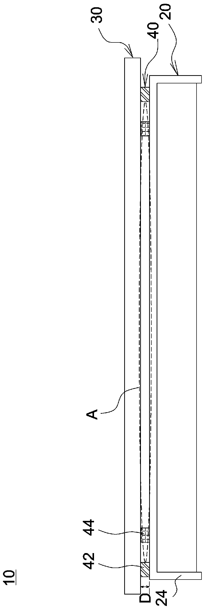
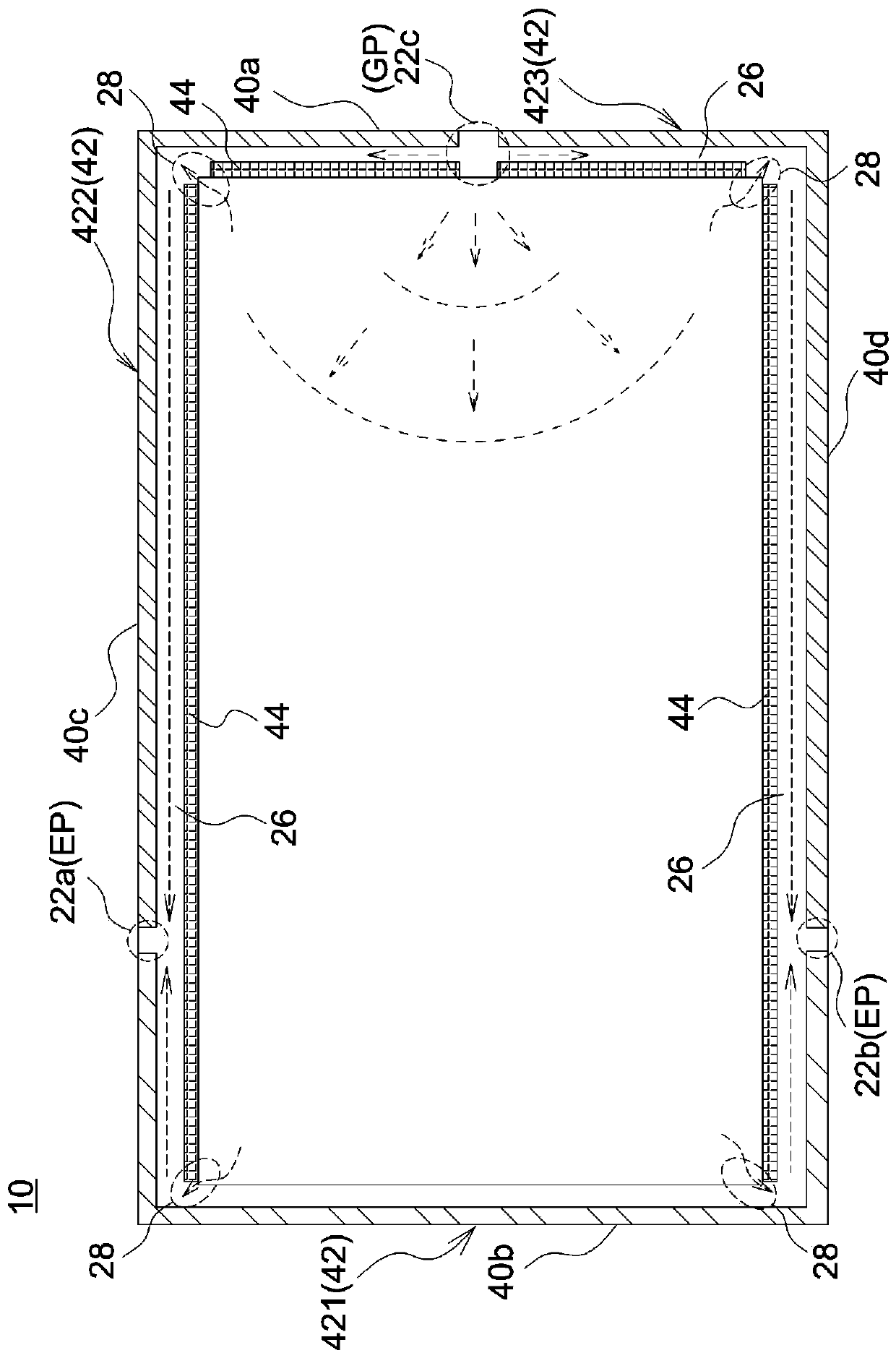
[0016] figure 2 It is a schematic diagram of a touch display device according to an embodiment of the present invention. image 3 It is a schematic diagram of the sealing structure of an embodiment of the present invention. Such as figure 2 As shown, the touch display device 10 includes a display panel 20 , a touch panel 30 and a sealing structure 40 . The display panel 20 is arranged on one side of the touch panel 30 and forms a gap D with the touch panel 30, the sealing structure 40 is a...


PUM


Abstract

The invention provides a touch display device. The touch display device comprises a touch panel, a display panel and a glue sealing compound structure, the glue sealing structure is arranged between the touch panel and the display panel and defines a glue injection area, and the glue sealing structure comprises a plurality of first retaining walls and a plurality of second retaining walls. The first retaining walls are arranged on the periphery of the glue injection area and at least define a first edge, a second edge, a third edge and a fourth edge, the first edge and the second edge are opposite to each other, the third edge and the fourth edge are opposite to each other, and the third edge and the fourth edge are arranged to form at least one notch respectively. The plurality of first retaining walls are formed by double faced adhesive tape, and the plurality of second retaining walls are arranged on the inner sides of the plurality of first retaining walls and define at least one diversion trench with the plurality of first retaining walls.

Description

technical field [0001] The invention relates to a touch display device and a bonding method for the touch display device. Background technique [0002] Among the bonding methods adopted by the current touch display devices, a common method is to inject optical glue into the sealing structure of the display panel and the touch panel to bond the display panel and the touch panel. Such as figure 1 As shown, in the glue injection bonding process of a conventional touch display device 100, a double-sided adhesive strip 102 is usually used to separate the display panel and the touch panel, and then an outer retaining wall is arranged inside the double-sided adhesive strip 102. 104 and an inner retaining wall 106, the flow channel is defined by the outer retaining wall 104 and the inner retaining wall 106, and then the glue injection operation is performed. However, in a conventional design example, the width of the double-sided adhesive tape 102 can be 1.0 mm, the sum of the wid...

Claims


Application Information

Patent Timeline
IPC IPC(8): G06F3/041
CPCG06F3/0412G06F2203/04103
Inventor 张敏
Owner CORETRONIC DISPLAY SUZHOU CO LTD
Learn More