Shell stamping device for machining motor

A technology of punching device and casing, applied in the direction of feeding device, positioning device, storage device, etc., can solve the problems of low punching efficiency, inability to realize efficient punching operation, etc., and achieve the effect of improving punching efficiency

Inactive Publication Date: 2020-08-07
黄国普
View PDF11 Cites 14 Cited by
  • Summary
  • Abstract
  • Description
  • Claims
  • Application Information

AI Technical Summary

Problems solved by technology

[0003] The patent application publication number CN106849560 A discloses a new type of stamping equipment for motor processing. The rotating rod is installed on the frame, the axle of the eccentric wheel is installed on the rotating rod, and the driven wheel is installed on the On the rotating rod, the frame is arranged on the outside of the eccentric wheel, the upper end of the frame is provided with an upper pole and the lower end is provided with a lower pole, and the upper fixing sleeve is installed on the frame And it is sleeved on the outside of the upper pole, the lower fixing sleeve is installed on the frame and it is sleeved on the outside of the lower pole, and the limiting p...

Method used


Image

  • Shell stamping device for machining motor
  • Shell stamping device for machining motor
  • Shell stamping device for machining motor

Examples


Embodiment 1

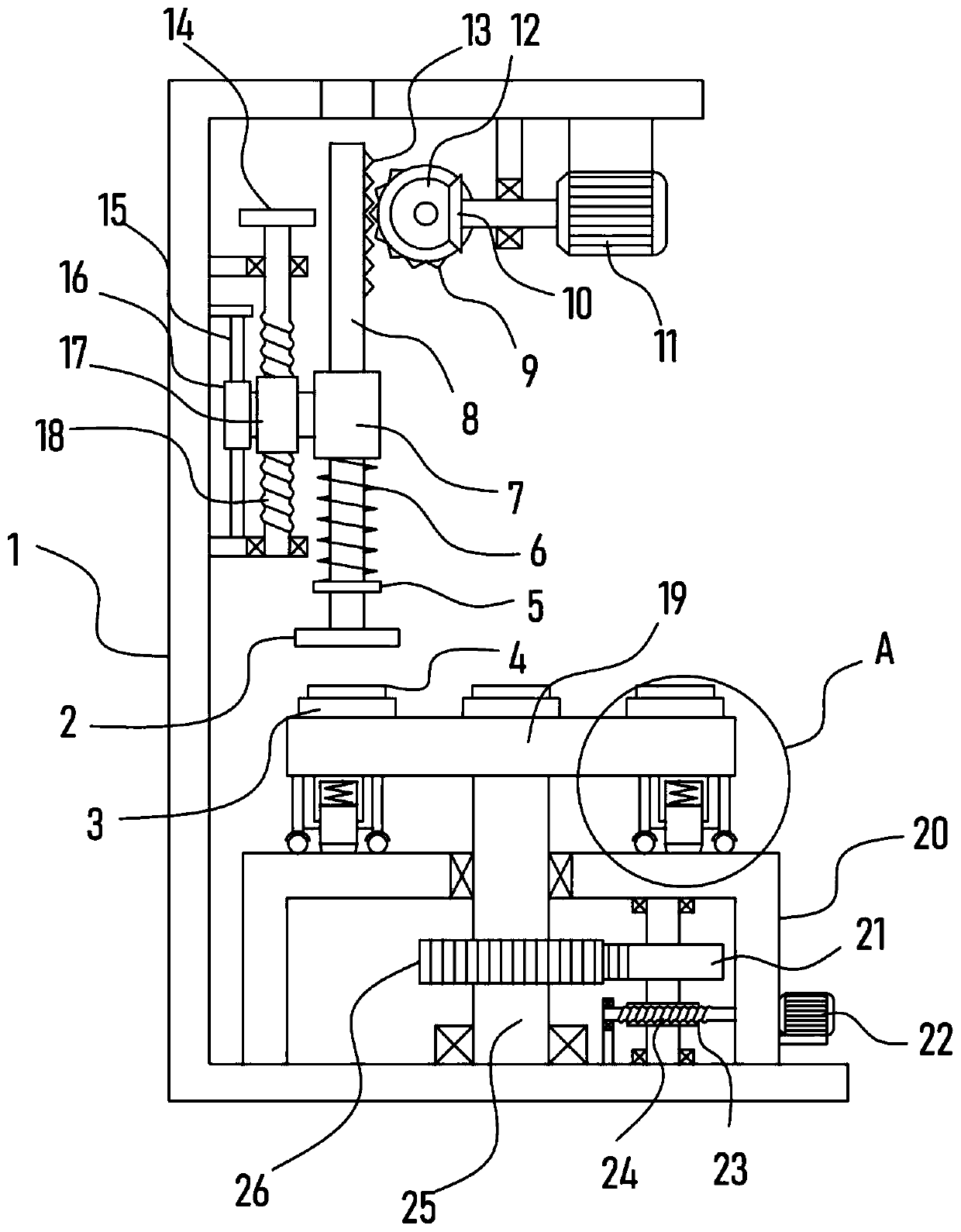
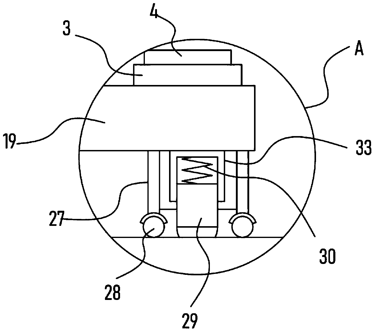
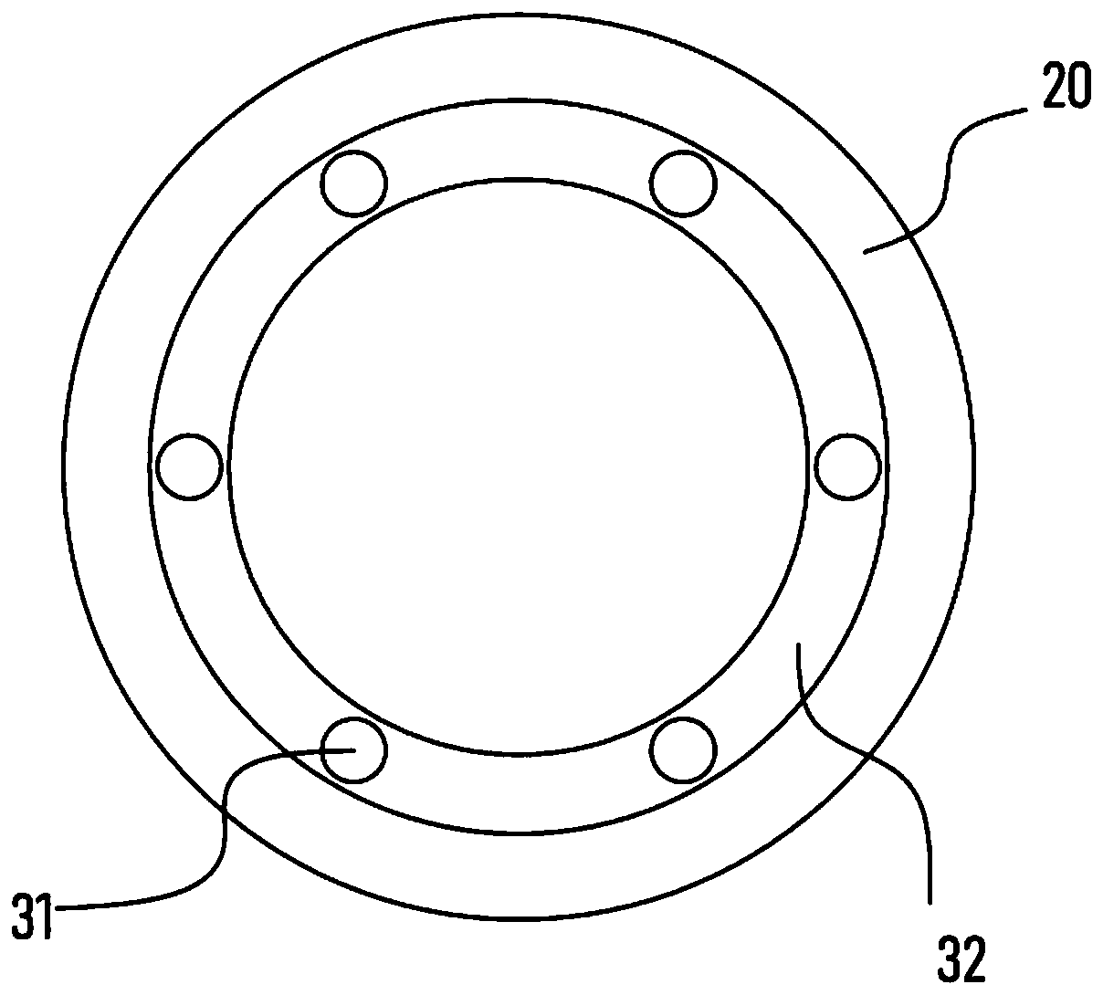
[0025] see Figure 1-4 , a shell stamping device for motor processing, comprising a support frame 1, a fixed frame 20 is fixed on the support frame 1, a motor II22 is fixed on the side wall of the fixed frame 20, and a vertically arranged steering shaft is rotatably mounted on the fixed frame 20 25. The upper end of the steering shaft 25 is vertically fixed with a turntable 19, and the fixed frame 20 is provided with a rotating mechanism for driving the steering shaft 25 to rotate step by step. The turntable 19 is uniformly fixed with several support blocks 3 in the upper direction. A lower mold 4 is fixedly installed on the support block 3, an elastic positioning mechanism is arranged between the turntable 19 and the fixed frame 20, a motor I11 is fixed on the support frame 1, and a vertical lifting mechanism is driven and connected to the motor I11. The vertical lifting mechanism is connected with an upper mold 2 intermittently corresponding to the lower mold 4, and the supp...

Embodiment 2

[0031] On the basis of Embodiment 1, in addition, the rotating mechanism of this device comprises the steering gear 26 that is sheathed and fixed on the steering shaft 25, and the incomplete gear II21 that is intermittently meshed with the steering gear 26 is installed on the support frame 1 to rotate. The mechanism also includes a worm wheel 23 coaxially fixed with the incomplete gear II21, and a worm screw 24 meshed with the output shaft of the motor II22 through a coupling is connected to the worm wheel 23.

[0032] Through the above settings, the motor II22 is used to drive the worm 24 to rotate, and the worm 24 drives the incomplete gear II21 to rotate through the worm wheel 23 meshed with it. At this time, the incomplete gear II21 alternately meshes with the steering gear 26 to realize the cycle of the steering gear 26. Permanent rotation, that is, the lower mold 4 corresponds to the upper mold 2 one by one and realizes the stamping operation, which greatly improves the s...


PUM


Abstract

The invention discloses a shell stamping device for machining a motor, and relates to the technical field of motor machining. The shell stamping device comprises a supporting frame, an elastic positioning mechanism is arranged between a rotary disc and a fixed frame, a motor I is fixed to the supporting frame, the motor I is in driving connection with a vertical lifting mechanism, upper dies intermittently corresponding to lower dies are connected to the vertical lifting mechanism, and an adjusting mechanism is arranged on the supporting frame. According to the shell stamping device for machining the motor, the vertical lifting mechanism can drive a stamping rod to vertically rise and fall with the upper dies, and the stamping operation of the upper dies on motor shells of the lower dies is realized through elastic force of a spring ring; the adjusting mechanism can adjust the impact force that is the initial length of the spring ring, and sufficient stamping of the motor shells is convenient to realize; and the rotary disc can realize marching type rotation under the driving of a rotation mechanism, so that the motor shells of the multiple lower dies are subjected to stamping operation one by one, and the stamping efficiency of the motor shells is greatly improved.

Description

technical field [0001] The invention relates to the technical field of motor processing, in particular to a casing stamping device for motor processing. Background technique [0002] Motor English: Electric machinery, commonly known as "motor", refers to an electromagnetic device that realizes the conversion or transmission of electric energy according to the law of electromagnetic induction. The motor is represented by the letter M in the circuit, and the old standard is represented by D. Its main function is to generate driving torque as a power source for electrical appliances or various machines. The generator is represented by the letter G in the circuit. Its main function is Using mechanical energy to convert into electrical energy, in the process of motor processing, it is necessary to use a stamping device to stamp the motor casing. [0003] The patent application publication number CN106849560 A discloses a new type of stamping equipment for motor processing. The r...

Claims


Application Information

Patent Timeline
IPC IPC(8): B21D22/06B21D22/08B21D43/00B21D43/14
CPCB21D22/06B21D22/08B21D43/003B21D43/14
Inventor 黄国普
Owner 黄国普
Why Eureka
Try Eureka