Operation and control method applied to machine tool die
A control method and mold technology, applied to forming tools, mechanical equipment, manufacturing tools, etc., can solve the problems of high stamping force, different workpiece quality, waste of workers' working time, etc., to avoid working time, stable use, and avoid misalignment Effect
- Summary
- Abstract
- Description
- Claims
- Application Information
AI Technical Summary
Problems solved by technology
Method used
Image

Examples
Embodiment Construction
[0051] The technical solutions of the present invention will be further described below in conjunction with the accompanying drawings and through specific implementation methods.
[0052] Wherein, the accompanying drawings are only for illustrative purposes, showing only schematic diagrams, rather than physical drawings, and should not be construed as limitations on this patent; in order to better illustrate the embodiments of the present invention, some parts of the accompanying drawings will be omitted, Enlarged or reduced, does not represent actual product size.
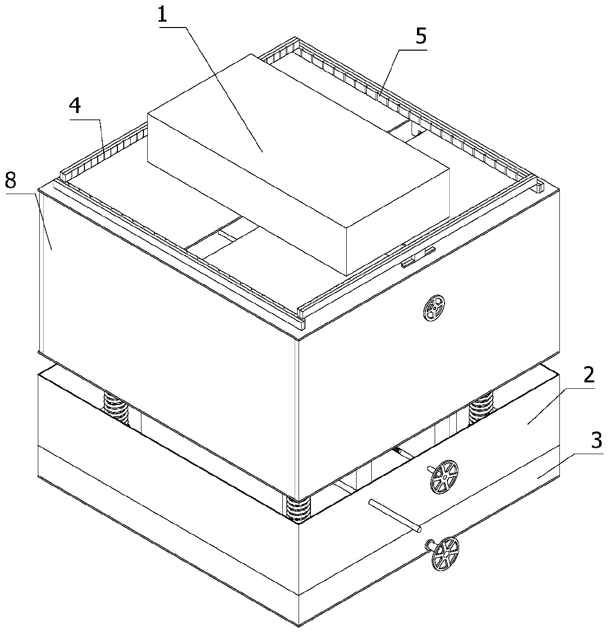
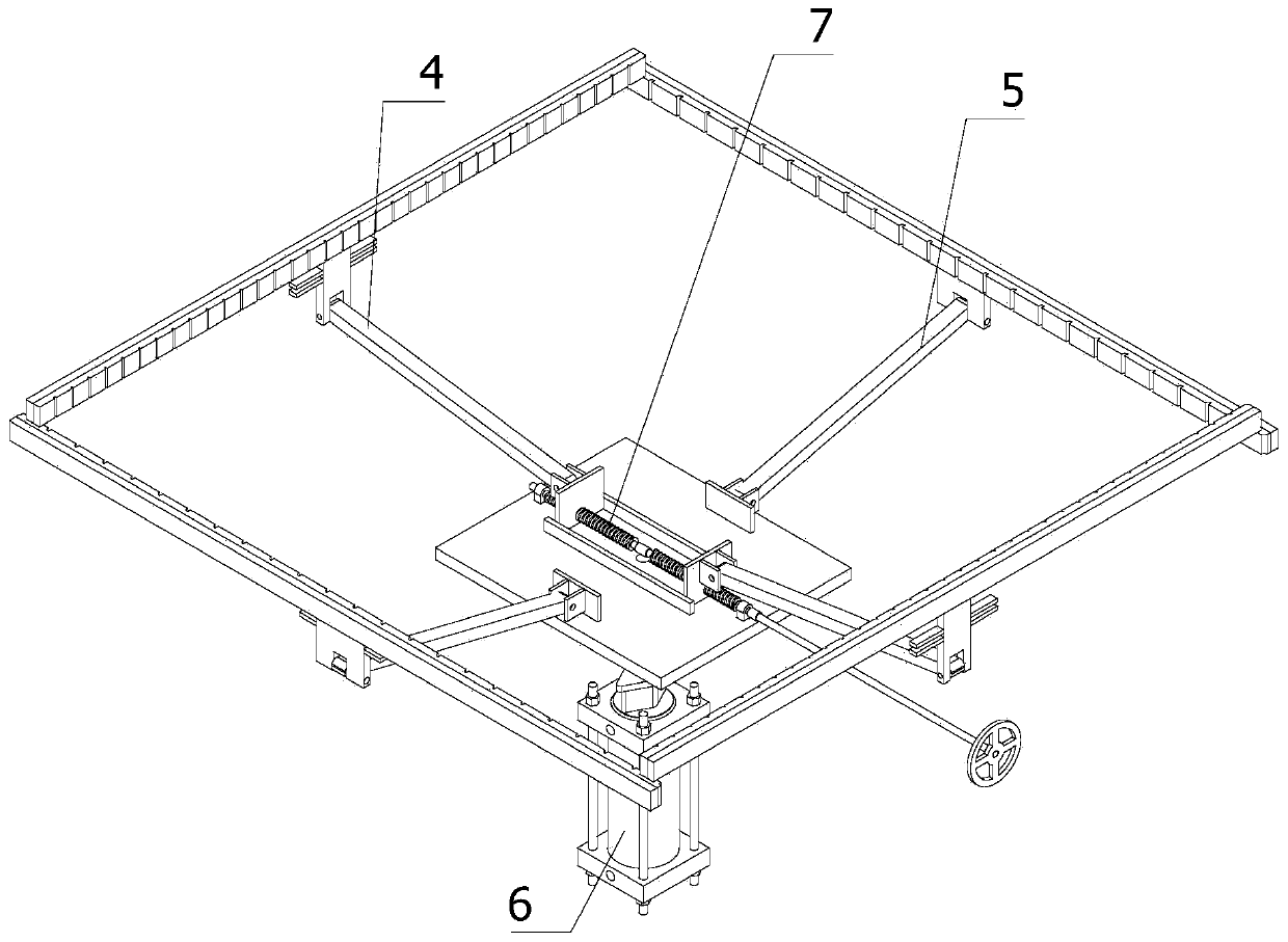
[0053] refer to Figure 1 to Figure 12 The machine tool mold operation and control device shown includes a stamping model 1, a shock absorbing mechanism 2, a lifting mechanism 3 and a clamping mechanism. The stamping model 1 is installed on the top of the clamping mechanism, and the shock absorbing mechanism 2 is fixedly installed on the clamping mechanism. At the bottom of the mechanism, the lifting mechanism 3 ...
PUM
 Abstract
Description
Claims
Application Information
PatSnap Eureka turns technology decisions into work you can execute. Powered by our Innovation Knowledge Graph, it runs expert workflows across engineering, life sciences, materials and intellectual property. Get your review-ready output in minutes.


