Balance arm device with shock absorption function and crane trolley provided with device
A balance arm and balancing technology, applied in the direction of load block, transportation and packaging, load suspension components, etc., can solve the problems of large selection, increase equipment cost, etc., reduce force, reduce force, improve safety and reliability sexual effect
- Summary
- Abstract
- Description
- Claims
- Application Information
AI Technical Summary
Problems solved by technology
Method used
Image
Examples
Embodiment 1
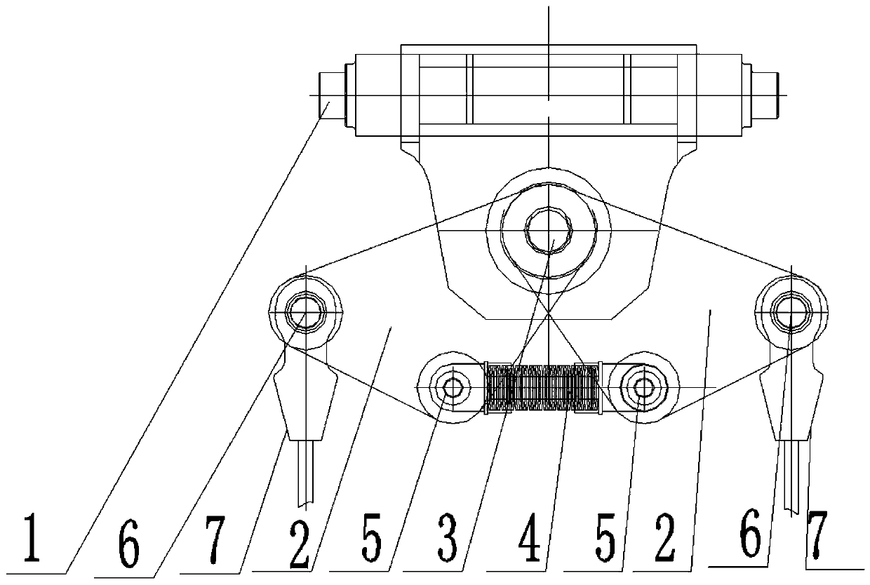
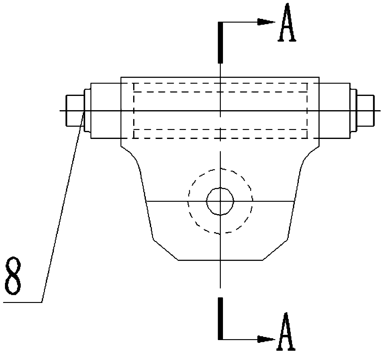
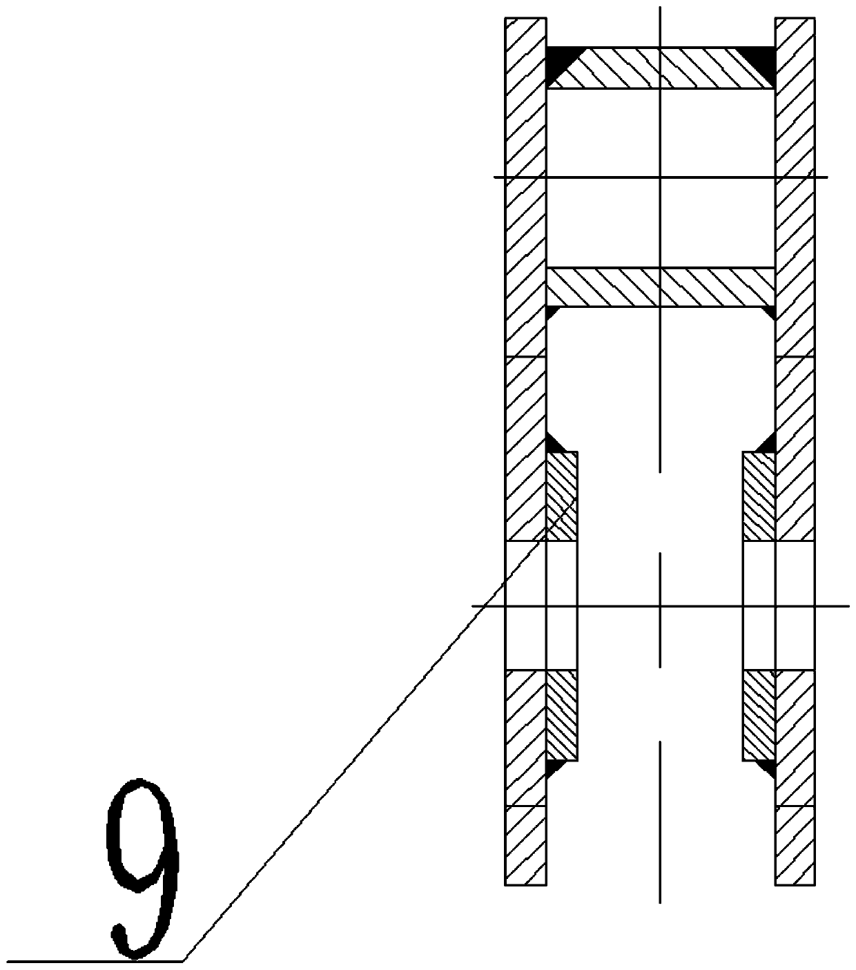
[0039] Such as Figure 1-7As shown, a balance arm device with shock absorption, the balance arm device 21 includes a balance arm frame 1 arranged horizontally, two balance beams 2 are symmetrically arranged on the left and right sides of the bottom of the balance arm frame 1, two The upper end of the balance beam 2 is connected to the lower part of the balance arm frame 1 through the same hinge shaft I3, and the bottom ends of the two balance beams 2 are connected by a disc spring group 4, and the disc spring The two ends of the group 4 are respectively connected to the balance beam 2 through the hinge shaft II5; the ends of the two bottoms of the two balance beams 2 away from each other are connected to the wire rope connection end 7 through the pin shaft 6, and the pin shaft 6 is higher than the The hinge axis II5 is lower than the hinge axis I3.
[0040] The balance arm frame 1 is welded into a box-shaped structure by steel plates, and the left and right ends of the upper ...
Embodiment 2
[0044] Such as Figure 1-10 As shown, a lifting trolley includes a car body 18, the bottom of the car body 18 is provided with a car body running mechanism 19, the middle part of the car body 18 has a balance arm device mounting seat 20, and the balance arm device The balance arm device 21 described in Embodiment 1 is installed in the mounting seat 20, and the connecting shaft 8 is rotationally connected with the balance arm device mounting seat 20; A lifting mechanism 23 that drives the reel 22 to rotate; a hook assembly 24 is arranged in the middle of the bottom of the vehicle body 18;
[0045] One end of the wire rope I25 is fixed on the left side of the reel 22, and the other end passes through the left moving pulley I26 fixed on the left side of the hook assembly 24, the direction changing pulley I27 fixed on the car body 18, The right movable pulley I28 fixed on the right side of the hook assembly 24 is fixedly connected with the wire rope connecting end 7 arranged on t...
PUM
 Abstract
Description
Claims
Application Information
 - R&D
- Intellectual Property
- Life Sciences
- Materials
- Tech Scout
- Unparalleled Data Quality
- Higher Quality Content
- 60% Fewer Hallucinations
Browse by: Latest US Patents, China's latest patents, Technical Efficacy Thesaurus, Application Domain, Technology Topic, Popular Technical Reports.
© 2025 PatSnap. All rights reserved.Legal|Privacy policy|Modern Slavery Act Transparency Statement|Sitemap|About US| Contact US: help@patsnap.com


