Circular glass cutting device

A cutting device, circular technology, applied in glass cutting devices, glass manufacturing equipment, manufacturing tools, etc., can solve the problems of low cutting efficiency, unable to ensure the maximum utilization of strip glass, etc., to reduce the generation of glass waste. Effect

Active Publication Date: 2020-08-07
南京俊佑光电科技有限公司
View PDF5 Cites 5 Cited by
  • Summary
  • Abstract
  • Description
  • Claims
  • Application Information

AI Technical Summary

Problems solved by technology

[0004] In order to overcome the disadvantages of being unable to ensure maximum utilization of strip glass, low cutting efficiency, and the need to manually push the glass plate intermittently, the technical problem to be solved is: to provide a glass plate that can automatically move intermittently, and the movement distance of the glass plate is the same. , a circular glass cutting device that can effectively reduce the generation of glass waste

Method used


Image

  • Circular glass cutting device
  • Circular glass cutting device
  • Circular glass cutting device

Examples


Embodiment 1

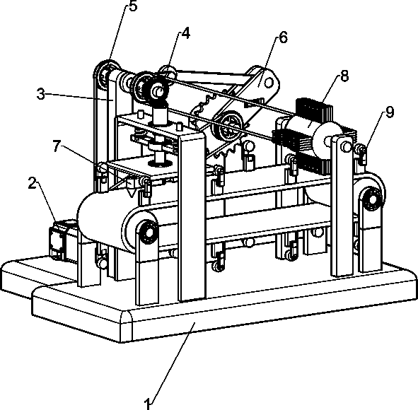
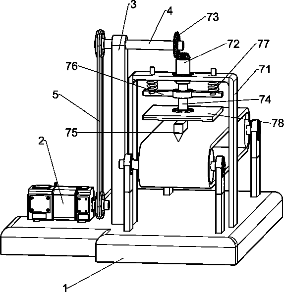
[0042] A circular glass cutting device such as figure 1 As shown, it includes a mounting base 1, a motor 2, a main shaft support frame 3, an output spindle 4, a first belt assembly 5, an intermittent motion mechanism 6 and a cutting mechanism 7, and the left front part of the mounting base 1 is equipped with a motor 2, and the mounting base 1. There is a main shaft support frame 3 on the left front. The main shaft support frame 3 is located on the right side of the motor 2. The upper part of the main shaft support frame 3 is rotatably connected to the output main shaft 4. There is a first shaft between the output shaft of the motor 2 and the left end of the output main shaft 4. The belt assembly 5 and the intermittent motion mechanism 6 are arranged on the left rear portion of the mounting base 1 and the output main shaft 4 , and a cutting mechanism 7 is arranged on the right front side of the mounting base 1 , and the cutting mechanism 7 is connected with the output main shaft...

Embodiment 2

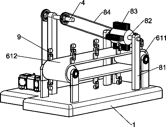
[0045] Overall, according to Figure 1-3 with Figure 5-6As shown in the diagram, the intermittent motion mechanism 6 includes a rotating rod 61, a connecting rod 62, a swing plate 63, a circular top block 64, a first spring 65, a support plate 66, an output rotating shaft 67, a ratchet 68, a first roller 69, The second belt assembly 610, the second drum 611 and the conveyor belt 612, the left side of the output main shaft 4 is equipped with a rotating rod 61, the rotating rod 61 is located on the right side of the main shaft support frame 3, the end of the rotating rod 61 is connected with a connecting rod 62 in a rotating manner, and the mounting seat 1. There is a support plate 66 at the rear of the left side. The upper part of the support plate 66 is connected to the output shaft 67 through a one-way bearing. A ratchet 68 is installed on the output shaft 67. A swing plate 63 is rotatably installed on the output shaft 67 on both sides of the ratchet 68. , the rear end of t...

Embodiment 3

[0050] Specifically, such as figure 1 with Figure 4 As shown, a cleaning mechanism 8 is also included, and the cleaning mechanism 8 includes a support rod 81, a large rotating drum 82, a hair brush 83 and a third belt assembly 84, and the left and right sides of the rear right side of the mounting base 1 are provided with a support rod 81, A large rotating drum 82 is installed in rotation between the upper parts of the support rods 81 on both sides, and a plurality of brushes 83 are evenly arranged on the outside of the large rotating drum 82, and a third brush 83 is connected between the right side of the output main shaft 4 and the left side of the large rotating drum 82. Belt assembly 84.

[0051] After the motor 2 is started, the motor 2 drives the output spindle 4 to rotate, and the output spindle 4 drives the large rotating drum 82 to rotate through the third belt assembly 84, and the brush 83 on the outside of the large rotating drum 82 cleans the surface of the strip...


PUM


Abstract

The invention relates to a cutting device, in particular to a circular glass cutting device. The technical problem to be solved is to provide the circular glass cutting device which can realize automatic intermittent movement of a glass plate, does not need manual operation and improves the cutting efficiency. According to the technical scheme, the circular glass cutting device comprises: a mounting base, wherein a motor is mounted on the side portion of the mounting base, and a main shaft supporting frame is arranged on the side, close to the motor, of the mounting base; the output main shaftthat is rotatably arranged at the upper part of the main shaft supporting frame far away from one side of the motor, and the end part of the output main shaft close to one side of the motor penetrates through the main shaft supporting frame. The intermittent movement mechanism drives the long-strip-shaped glass plate to move intermittently, the long-strip-shaped glass plate does not need to be pushed manually and intermittently, and automatic cutting of round glass is achieved through the cutting mechanism, meanwhile, under the action of the supporting rolling wheels, a conical cutting knifecan move upwards automatically when the long-strip-shaped glass plate moves.

Description

technical field [0001] The invention relates to a cutting device, in particular to a circular glass cutting device. Background technique [0002] Now, workers usually cut circular glass on a long glass plate. The worker presses and turns the cutting knife, and the cutting knife then draws a circle on the glass plate. The circular glass is cut out. After cutting a circular glass, The worker stops pressing the cutter and then pushes the long strip of glass to the left, when the uncut area of ​​the glass is under the cutter, the worker continues to press down and turn the cutter, the cutter draws another circle on the glass , another circular glass is cut out, and the worker repeats the above operations to cut the long glass plate into multiple circular glasses. [0003] The above method of manually cutting circular glass plates requires workers to push the glass plates intermittently. Manual movement results in different moving distances each time, which cannot guarantee the ...

Claims


Application Information

Patent Timeline
Patent Type & Authority Applications(China)
IPC IPC(8): C03B33/04
CPCC03B33/04Y02P40/57
Inventor 黄志军
Owner 南京俊佑光电科技有限公司
Why Eureka
Try Eureka