
A textile lifting device

A pulling device and textile technology, applied in textiles, textiles, papermaking, jacquard machines, etc., can solve the problems of spinning thread breakage, affecting the textile efficiency of textiles, and different spinning thread tenacity, so as to avoid breakage and avoid spinning thread separation. , the effect of reducing wear

Active Publication Date: 2021-12-14
杭州红伟丝绸有限公司
View PDF9 Cites 0 Cited by
  • Summary
  • Abstract
  • Description
  • Claims
  • Application Information

AI Technical Summary

Problems solved by technology

[0005] The purpose of the present invention is to solve the disadvantages in the prior art that "due to the different toughness of the yarns of different thicknesses and materials, when the pulling force is too large, it is easy to cause the yarns to break, thereby affecting the weaving efficiency of textiles" , and propose a textile lifting device

Method used

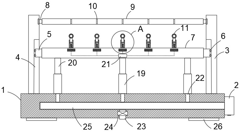
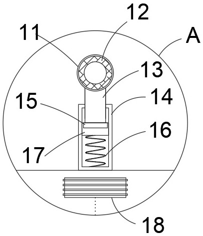
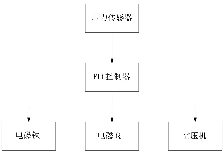

Image

  • A textile lifting device
  • A textile lifting device
  • A textile lifting device

Examples


Embodiment Construction

[0024] The following will clearly and completely describe the technical solutions in the embodiments of the present invention with reference to the accompanying drawings in the embodiments of the present invention. Obviously, the described embodiments are only some, not all, embodiments of the present invention.

[0025] In describing the present invention, it should be understood that the terms "upper", "lower", "front", "rear", "left", "right", "top", "bottom", "inner", " The orientation or positional relationship indicated by "outside", etc. is based on the orientation or positional relationship shown in the drawings, and is only for the convenience of describing the present invention and simplifying the description, rather than indicating or implying that the referred device or element must have a specific orientation, so as to Specific orientation configurations and operations, therefore, are not to be construed as limitations on the invention.

[0026] In the present inv...


PUM


Abstract

The invention discloses a textile lifting device, comprising a base, on which a mounting side plate is symmetrically and fixedly connected, the mounting side plate is connected to a rotating shaft through a ball bearing, and a guide roller is fixedly interspersed on the rotating shaft, A plurality of sealing cylinders are fixedly connected to the base, and the plurality of sealing cylinders are arranged at equal intervals. A piston block is slidably connected to each sealing cylinder, and a push rod is fixedly connected to the piston block. The upper end of the push rod is fixedly connected with a lifting plate, the lifting plate is fixedly connected with sleeve rods at equal intervals, and each sleeve rod is slidably connected with a permanent magnet guide block. In the present invention, the PLC controller controls each electromagnet to reduce the current input, so that the magnetic force is weakened, and the suction force on the permanent magnet guide block is reduced, so that the spring drives the permanent magnet guide block to slide upward, so that the lifting ring moves upward, reducing the force on the spinning ring. Thread pressure to avoid yarn breakage.

Description

technical field [0001] The invention relates to the technical field of a textile lifting device, in particular to a textile lifting device. Background technique [0002] China is one of the first countries in the world to produce textiles. As early as in the primitive society, people had already collected wild kudzu, hemp, silk, etc., and used the feathers of birds and animals they hunted to knead, weave, weave, and weave them into rough clothes. Instead of grass blades and animal hides for covering the body. In the later period of primitive society, with the development of agriculture and animal husbandry, people gradually learned the methods of artificial production of textile raw materials, such as planting hemp, raising sheep for wool, and silkworm breeding, and used more tools. Some tools are already composed of several parts, while others have several uses for one part, which greatly improves labor productivity. Textiles at that time had patterns and colors. However...

Claims


Application Information

Patent Timeline
Patent Type & Authority Patents(China)
IPC IPC(8): D03C3/26
CPCD03C3/26
Inventor 李新花
Owner 杭州红伟丝绸有限公司
Learn More