Discharging mechanism and assembling system
A technology of a discharging mechanism and a pushing device, which is applied in the field of industrial manufacturing, can solve the problems of ineffective positioning of long U copper pipes, low pipe penetration efficiency, and easy failure, so as to avoid material jamming or damage, avoid structural interference, and achieve good The effect of guiding
- Summary
- Abstract
- Description
- Claims
- Application Information
AI Technical Summary
Problems solved by technology
Method used
Image
Examples
Embodiment 1
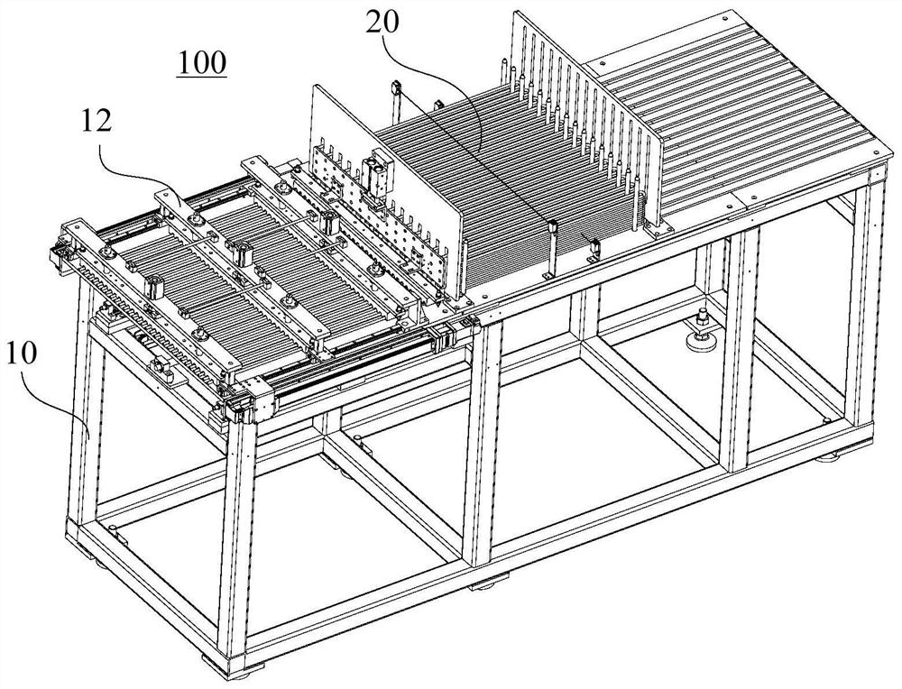
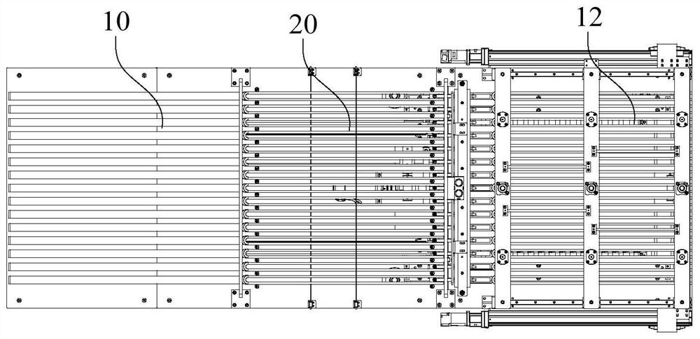
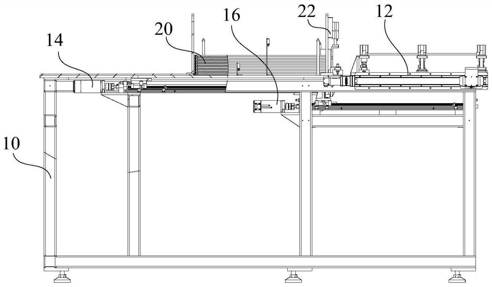
[0072] Such as Figure 1 to Figure 3 As shown, an embodiment of the present invention proposes a discharge mechanism 100 , wherein a storage bin 20 is provided on the frame 10 . Both sides of storage bin 20 are respectively provided with guiding device 12 and first material pushing device 14, and the bottom of frame 10 is provided with second material pushing device 16; The pushing device cooperates with each other to push the material to a designated position; the guiding device 12 plays a good guiding and limiting role in the pushing process, avoiding the situation of material jamming or crushing.
[0073] Specifically, materials are stored in the storage bin 20, and the first pushing device 14 is used to push the materials in the storage bin 20 to the guide device 12; Continue to push the material to push the material to the designated position; the guiding device 12 cooperates with the second pushing device 16 to play a guiding role in the process of pushing the second pu...
Embodiment 2
[0076] Such as Figure 1 to Figure 3As shown, another embodiment of the present invention proposes a discharge mechanism 100 , wherein a storage bin 20 is provided on the frame 10 . Both sides of the storage bin 20 are provided with a guide device 12 and a first pushing device 14 respectively, and a second pushing device 16 is arranged below the frame 10; the first pushing device 14 is used to push the material in the storage bin 20 To the guide device 12; the second pushing device 16 cooperates with the guide device 12 to move the material to a designated position; as Figure 4 As shown, the first pushing device 14 includes a first driving part 142 and a pushing part 144, and the first driving part 142 drives the pushing part 144 to push the material.
[0077] In this embodiment, during the working process of the first pushing device 14, the first driving member 142 drives the pushing part 144 to move toward the storage bin 20, and pushes the bottom layer of material in the ...
Embodiment 3
[0083] Such as Figure 1 to Figure 3 As shown, another embodiment of the present invention proposes a discharge mechanism 100 , wherein a storage bin 20 is provided on the frame 10 . Both sides of storage bin 20 are respectively provided with guiding device 12 and first pushing device 14, and the bottom of frame 10 is provided with second pushing device 16; Push to the guide device 12; the second pusher device 16 cooperates with the guide device 12 to move the material to a designated position; as Figure 6 As shown, the second pushing device 16 includes a lifting part and a pushing part, and the pushing part can be lifted up and down driven by the lifting part.
[0084] In this embodiment, the second pushing device 16 includes a lifting part and a pushing part, and the pushing part can be lifted up and down driven by the lifting part. Before the second pushing device 16 pushes the material, the pushing part is hidden under the frame 10 to ensure that the first pushing devic...
PUM
 Abstract
Description
Claims
Application Information
 - R&D
- Intellectual Property
- Life Sciences
- Materials
- Tech Scout
- Unparalleled Data Quality
- Higher Quality Content
- 60% Fewer Hallucinations
Browse by: Latest US Patents, China's latest patents, Technical Efficacy Thesaurus, Application Domain, Technology Topic, Popular Technical Reports.
© 2025 PatSnap. All rights reserved.Legal|Privacy policy|Modern Slavery Act Transparency Statement|Sitemap|About US| Contact US: help@patsnap.com


