Supercharge Your Innovation With Domain-Expert AI Agents!

Method for preventing grouting hollowing in steel structure base

A steel structure, hollowing technology, applied in the direction of infrastructure engineering, construction, etc., can solve the problems that affect the strength and quality of the steel structure base, high-strength grouting material pouring into the hollowing, and it is difficult to ensure that the grouting material is dense, etc., to achieve ideas and methods Clear, low cost, avoid rework effects

Pending Publication Date: 2020-08-07
MCC5 GROUP CORP SHANGHAI
View PDF0 Cites 0 Cited by
  • Summary
  • Abstract
  • Description
  • Claims
  • Application Information

AI Technical Summary

Problems solved by technology

[0005] Due to the criss-crossing of stiffened plates inside the steel structure base of this structure, although the addition of stiffened plates and supports makes the bottom steel plate, the top steel plate itself, and the relationship between the bottom steel plate and the top steel plate have higher strength , but the grouting of the internal grout of the steel structure base has encountered difficulties. The usual grouting methods are often difficult to ensure the density of the grout in each chamber, but often appear hollow, which affects the final strength and quality of the steel structure base. Become one of the difficult problems in the construction of steel structure base
[0006] For the problem that high-strength grouting material pouring inside the steel structure base is prone to hollowing, there is no good solution and direct technical inspiration in the prior art

Method used


Image

  • Method for preventing grouting hollowing in steel structure base
  • Method for preventing grouting hollowing in steel structure base

Examples


Embodiment

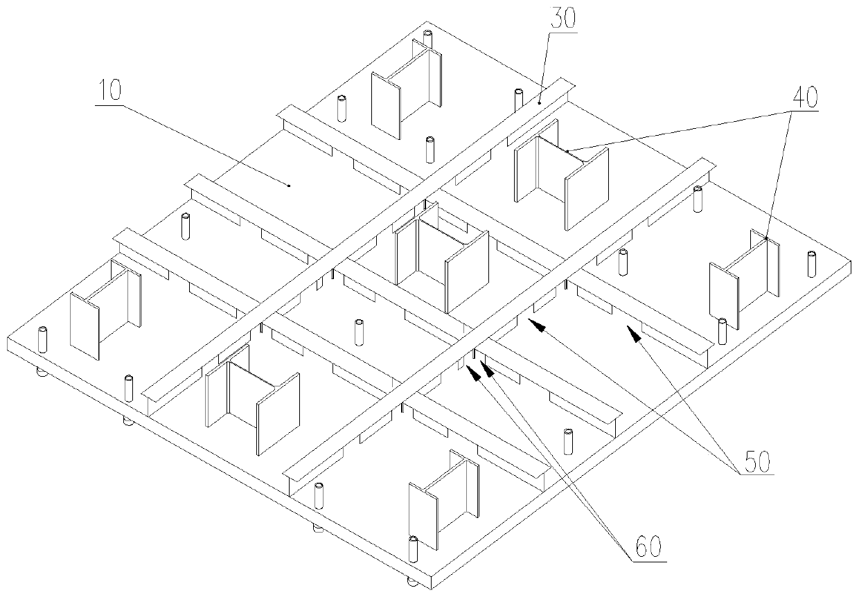
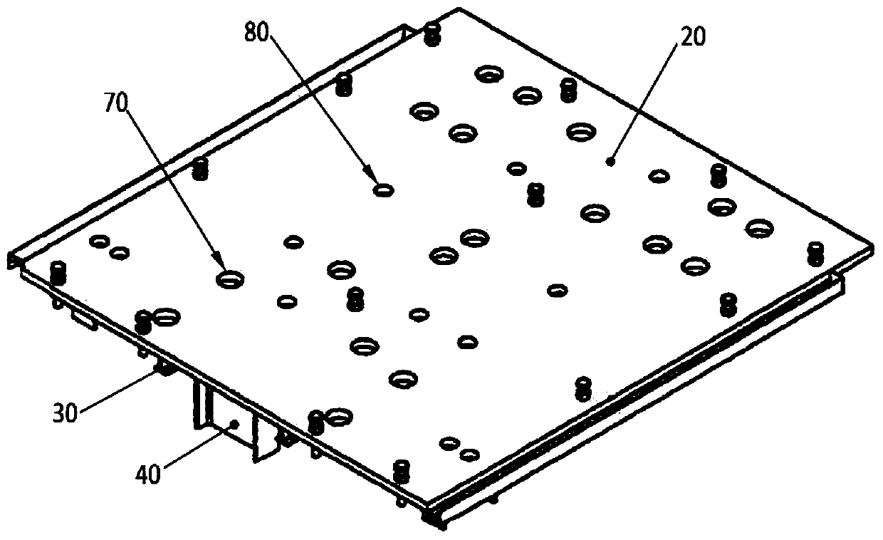
[0043] like figure 1 Schematic diagram of the structure of the steel plate at the bottom of the steel structure box in a method for preventing grouting hollowing inside the steel structure base provided by the embodiment of the present invention, figure 2 A schematic diagram of the structure of the top steel plate of the steel structure box in a method for preventing grouting hollowing inside the steel structure base provided by the embodiment of the present invention:

[0044] A method for preventing hollow grouting inside a steel structure base;

[0045] The steel structure base includes a steel structure box formed by combining the bottom steel plate 10 and the top steel plate 20. Inside the steel structure box is a high-strength grout that needs to be densely poured. The bottom steel plate 10 is laid and fixed on the reinforced concrete foundation structure layer, and the top layer The upper surface of the steel plate 20 is used for installing and carrying other equipmen...


PUM

PropertyMeasurementUnit
Diameteraaaaaaaaaa
Diameteraaaaaaaaaa

Abstract

The invention provides a method for preventing grouting hollowing in a steel structure base. The optimization measure for an internal structure of a steel structure box, the optimization measure for atop steel plate structure of the steel structure box and the optimization measure for the grouting method in the steel structure box are included. The method comprises the steps that flow assisting holes are formed in each polygonal cavity formed by stiffened plates through cross-connection in the steel structure box, vent holes are formed in a top steel plate of the steel structure box, the initial height of high-strength grouting materials is increased, the flow rate of the high-strength grouting materials is improved during grouting operation, the flow assisting holes are formed in two sides of the cross connection positions of the stiffened plates, and the vent holes are located at the included corners of each polygonal cavity to ensure that the polygonal cavities are filled with thehigh-strength grouting materials, no hollowing exists, the hollowing problem of the high-strength grouting materials inside the steel structure base is completely solved, ideas and methods for discovering and solving problems are clear, novel and unique, and the specific measures are simple, effective, low in cost but excellent in effect.

Description

technical field [0001] The invention relates to a grouting method for high-strength grouting material, in particular to a method for preventing hollow grouting inside a steel structure base, and belongs to the technical field of infrastructure construction. Background technique [0002] In some special structures, especially some buildings that need to install large-scale mechanical equipment and facilities, steel structure bases need to be set to meet the needs of special buildings or large-scale mechanical equipment and facilities installation. [0003] This type of steel structure base is usually built on the reinforced concrete base structure layer, which is a steel structure box filled with high-strength grouting material (referred to as slurry for short). [0004] The steel structure box usually includes a bottom steel plate and a top steel plate. The bottom steel plate is laid and fixed on the reinforced concrete base structure layer. On the respective steel plate sur...

Claims


Application Information

Patent Timeline
IPC IPC(8): E02D15/02
CPCE02D15/02
Inventor 孙毅仁
Owner MCC5 GROUP CORP SHANGHAI
Features
  • R&D
  • Intellectual Property
  • Life Sciences
  • Materials
  • Tech Scout
  • Unparalleled Data Quality
  • Higher Quality Content
  • 60% Fewer Hallucinations
Learn More