
Hinge door throwing device

A technology for hinged doors and hinged joints, applied in door/window accessories, aircraft accessories, wing fan components, etc., can solve the problems affecting the life of the throwing device, unsightly, and the adjustment of throwing force.

Active Publication Date: 2020-08-07
CHINA HELICOPTER RES & DEV INST
View PDF8 Cites 3 Cited by
  • Summary
  • Abstract
  • Description
  • Claims
  • Application Information

AI Technical Summary

Problems solved by technology

In the existing technical solutions, the main mechanism of the throwing device is arranged on the side where the hinge is located, but the hinge is usually arranged outside, so that exposure to the atmospheric environment will affect the life of the throwing device, and there are also unsightly problems, etc.
In addition, the current throwing device is difficult to adjust the size of the throwing force, and the throwing force is easily affected by the manufacturing accuracy and assembly accuracy of the parts, so the use is affected

Method used


Image

  • Hinge door throwing device
  • Hinge door throwing device
  • Hinge door throwing device

Examples


Embodiment Construction

[0018] In order to understand the objectives, technical solutions and advantages of the present invention more clearly, the present invention will be further described in detail below with reference to the accompanying drawings and embodiments.

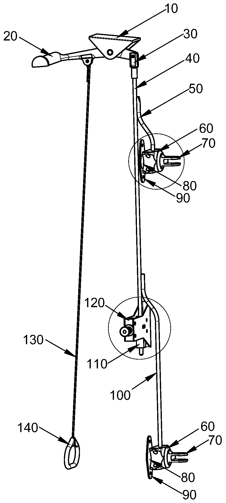
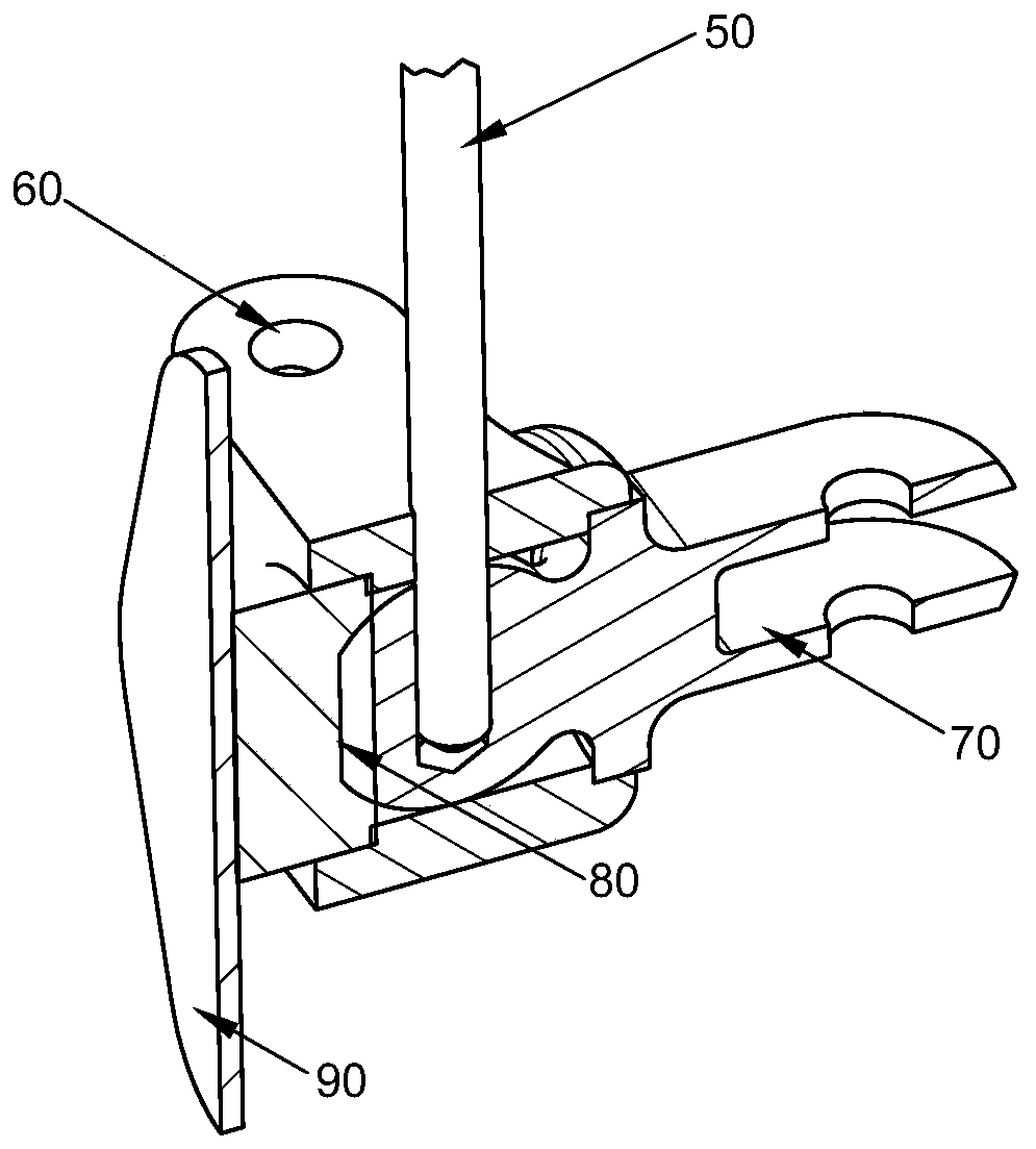
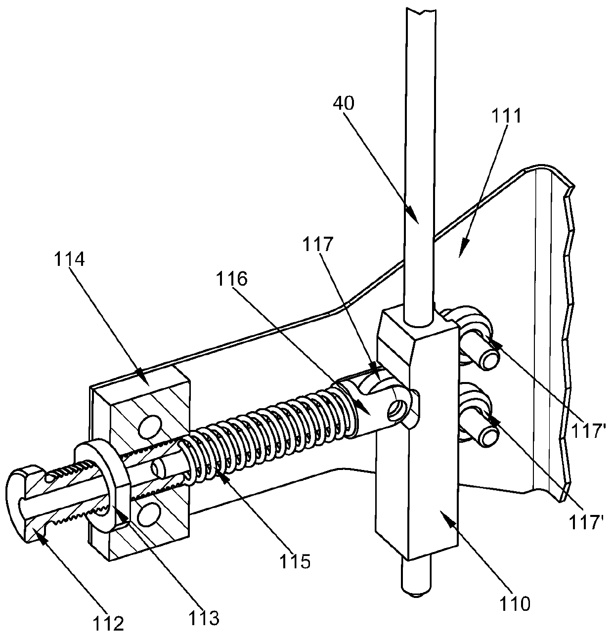
[0019] figure 1 is the structural schematic diagram of the hinged door throwing device of the present invention, figure 2 and 3 respectively figure 1 An enlarged schematic cross-sectional view of the part surrounded by circles in the upper middle and the part surrounded by circles in the lower part. As shown in the figure, in the hinged door throwing device of the present invention, the fixed support 10 is connected and fixed with the fixed structure (such as the frame, beam, etc. of the aircraft body), and the fixed support 10 has double ears, and the ears are connected to the upper throwing The middle position of the handle 20 is connected by a pin, and the upper throwing handle 20 can rotate around the axis of the pin. The adj...


PUM


Abstract

The invention relates to a hinge door throwing device. The hinge door throwing device comprises an upper throwing handle (20), a throwing adjusting rod (40), an upper throwing connector assembly, a lower throwing connector assembly and a throwing force adjusting device (120). The upper throwing handle (20) is hinged to a fixing structure. The throwing adjusting rod (40) is hinged to one end of theupper throwing handle (20). The throwing adjusting rod (40) is fixedly provided with an upper lock pin (50) and a lower lock pin (100) which are detachably inserted into the upper throwing connectorassembly and the lower throwing connector assembly correspondingly, and accordingly hinge connectors (70) connected with a hinge of a hinge door in the upper throwing connector assembly and the lowerthrowing connector assembly are fixed. The throwing force adjusting device (120) clamps the throwing adjusting rod (40), and the clamping force of the throwing force adjusting device (120) can be adjusted. The hinge door throwing device meets the throwing requirement in an emergency state, a main mechanism of the throwing device is arranged on the other side of the hinge, protection of the throwing device is achieved, and meanwhile the throwing force can be adjusted.

Description

technical field [0001] The invention belongs to the technical field of structural design, and in particular relates to a hinged door throwing device. Background technique [0002] When an accident occurs in a building or an aircraft, the door lock mechanism is prone to dislocation and deformation, which may cause the door lock to fail and fail to achieve emergency evacuation. When an accident occurs, the throwing of the door can quickly separate the door from the structure to meet the emergency evacuation needs. The currently commonly used technical solution for throwing the door is to disengage the hinge joint on the door from the hinge joint on the fixed structure during throwing. In the existing technical solution, the main mechanism of the throwing device is arranged on the side where the hinge is located, but the hinge is usually arranged outside, so that exposure to the atmospheric environment will affect the life of the throwing device, and there are also problems su...

Claims


Application Information

Patent Timeline
IPC IPC(8): E05D7/12B64C1/14
CPCB64C1/14E05D7/12E05D2007/126E05Y2900/502
Inventor 杨丰李成行王春辉邵家庆郝欣欣洪斌
Owner CHINA HELICOPTER RES & DEV INST
Learn More