
Hard disk fixing device based on electromagnetic induction principle

A hard disk fixing device and electromagnetic induction technology, applied in the direction of electrical digital data processing, data processing power supply, digital processing power distribution, etc., can solve problems such as poor heat dissipation, hard disk not configured, damaged hard disk, etc., to ensure normal operation and use effect , Guarantee the effect of normal operation and service life

Inactive Publication Date: 2020-08-07
杭州根基科技有限公司
View PDF4 Cites 1 Cited by
  • Summary
  • Abstract
  • Description
  • Claims
  • Application Information

AI Technical Summary

Problems solved by technology

[0003] Some existing solid-state hard disk devices use fans to dissipate heat, but the fans usually bring external dust into the housing. If the dust falls directly on the hard disk, it may make it difficult to clean the dust on the surface of the hard disk. Long-term accumulation will cause hard disk performance to decline. To protect the hard disk, people usually install a fixed protective cover on the hard disk, but because the protective cover seals the hard disk too much, it will cause poor heat dissipation, and when the hard disk is running at an increased level, fan blades alone cannot meet the heat dissipation requirements, resulting in hard disk The performance is degraded; and when the hard disk starts to work, it is generally in high-speed rotation. If we suddenly turn off the power midway, it may cause violent friction between the magnetic head and the platter and damage the hard disk. However, the existing hard disk is often not equipped with corresponding protection. device

Method used


Image

  • Hard disk fixing device based on electromagnetic induction principle
  • Hard disk fixing device based on electromagnetic induction principle
  • Hard disk fixing device based on electromagnetic induction principle

Examples


Embodiment Construction

[0024] The following will clearly and completely describe the technical solutions in the embodiments of the present invention with reference to the accompanying drawings in the embodiments of the present invention. Obviously, the described embodiments are only some, not all, embodiments of the present invention. Based on the embodiments of the present invention, all other embodiments obtained by persons of ordinary skill in the art without making creative efforts belong to the protection scope of the present invention.

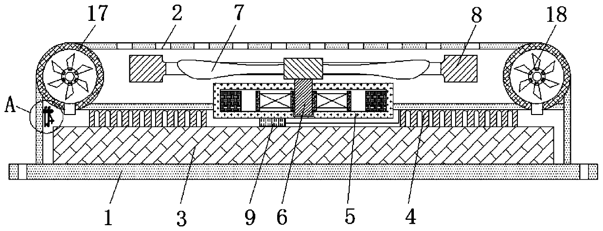
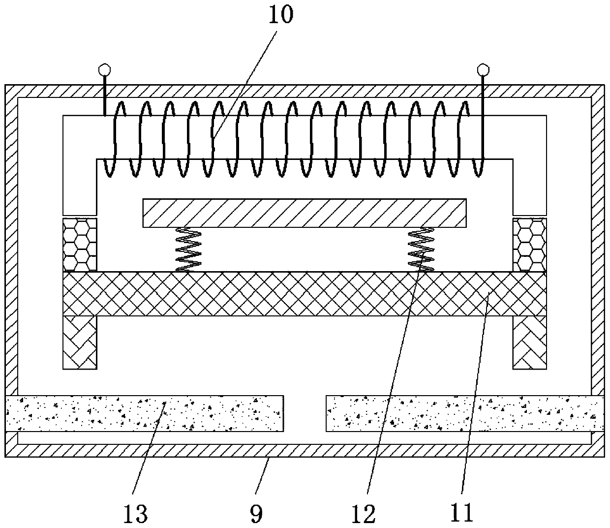
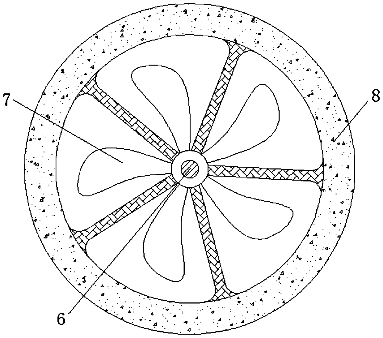
[0025] see Figure 1-4 , a hard disk fixing device based on the principle of electromagnetic induction, including a fixing frame 1, a heat dissipation hole 2, a solid state hard disk 3, a heat dissipation plate 4, a radiator 5, a central shaft 6, fan blades 7, an inertia wheel 8, a protector 9, an electromagnetic Rod 10, movable rod 11, return spring 12, connection contact block 13, bimetallic sheet 14, spring sheet 15, positioning sheet 16, refrigeration semi...


PUM


Abstract

The invention relates to the technical field of hard disks, and discloses a hard disk fixing device based on the electromagnetic induction principle. The device comprises a fixing frame, heat dissipation holes are formed in the top of the fixing frame, a solid state disk is connected into the fixing frame in a clamped mode, the interior of the fixing frame is fixedly connected with a heat dissipation plate, a radiator is fixedly connected to the interior of the fixed frame, a central shaft is movably connected to the interior of the radiator, fan blades are fixedly connected to the outer partof the central shaft, an inertia wheel is fixedly connected to the outer part of the central shaft, and a protector is fixedly connected to the exterior of the radiator. Through cooperative use of thefixing frame, the heat dissipation holes, the heat dissipation plate, the radiator, the central shaft and the fan blades, the effects of heat dissipation and dust prevention are achieved, dust is effectively prevented from entering the solid state disk, the effect of preliminary heat dissipation of the solid state disk is also achieved, normal operation and use effects of the fixed hard disk areguaranteed, and the service life of the solid state disk is also guaranteed.

Description

technical field [0001] The invention relates to the technical field of hard disks, in particular to a hard disk fixing device based on the principle of electromagnetic induction. Background technique [0002] The computer hard disk is the main storage device of the computer. The hard disk is composed of one or more aluminum or glass discs. These discs are covered with ferromagnetic materials. Most of the hard drives are fixed hard drives and are permanently sealed. Fixed in the hard disk drive, the early hard disk storage medium was replaceable, but today's typical hard disk is a fixed storage medium, sealed in the hard disk (except for a filter hole, used to balance the air pressure), with the development, can be Mobile hard disks have also appeared, and are becoming more and more popular, and there are more and more types. Hard disks are installed on most microcomputers. [0003] Some existing solid-state hard disk devices use fans to dissipate heat, but the fans usually ...

Claims


Application Information

Patent Timeline
Patent Type & Authority Applications(China)
IPC IPC(8): G06F1/18G06F1/20G06F1/30
CPCG06F1/187G06F1/20G06F1/30
Inventor 周坩
Owner 杭州根基科技有限公司
Learn More