Conveying device and method for laying cables through pipes

A conveying device and cable technology, applied in cable laying equipment, cable installation devices, cable installation and other directions, can solve the problems of large space occupation, high cost, difficult construction, etc. The effect of traction

Active Publication Date: 2022-04-12
SHANGHAI INT SUPERCONDUCTION TECH CO LTD
View PDF6 Cites 0 Cited by
  • Summary
  • Abstract
  • Description
  • Claims
  • Application Information

AI Technical Summary

Problems solved by technology

The friction between large cross-section power cables and cable pipes is greater, more conveyors are needed, and the space occupied by underground wells is also larger, which is not only not conducive to urban applications, but also brings high costs, construction difficulties and security issues

Method used


Image

  • Conveying device and method for laying cables through pipes
  • Conveying device and method for laying cables through pipes
  • Conveying device and method for laying cables through pipes

Examples


Embodiment 1

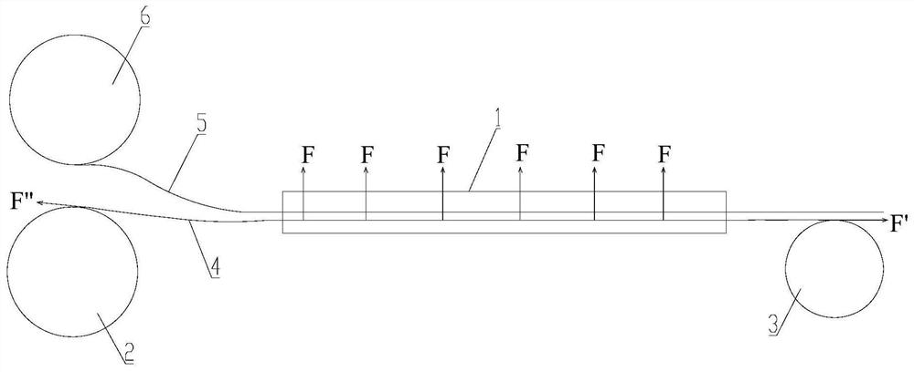
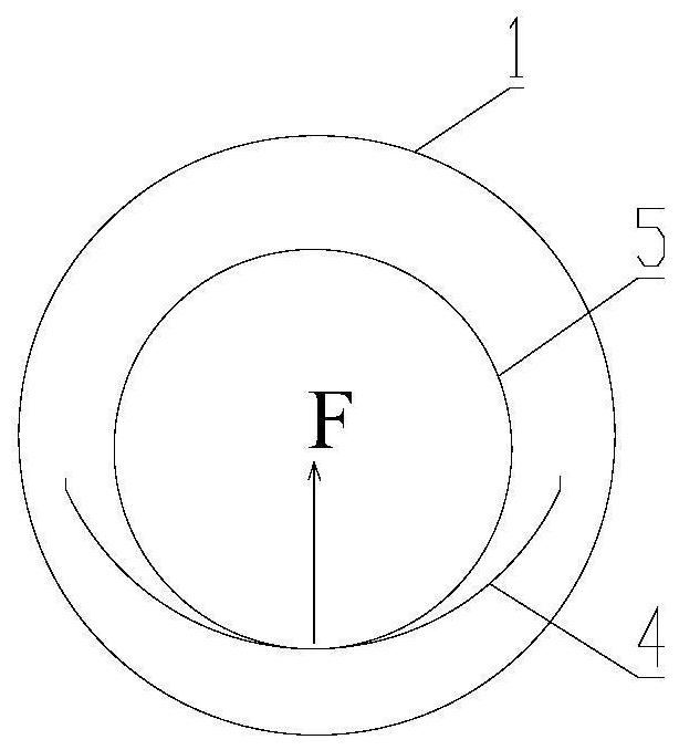
[0043] Such as figure 1 and figure 2 As shown, the first embodiment provides the first embodiment of the conveying device for laying cables through pipes of the present invention.

[0044] see figure 1 , The conveying device for cable pipe laying in the first embodiment includes a pay-off machine 2 , a take-up machine 3 and a conveyor belt 4 . Wherein, the pay-off machine 2 is placed at the entrance of the pipe 1, the pipe 1 is for the cable 5 to be laid to pass, the cable 5 to be laid is wound on the cable reel 6, and the cable reel 6 is placed at the entrance of the pipe 1, The cable 5 on the cable reel 6 can enter the pipe 1 from the entrance of the pipe 1 and protrude from the outlet of the pipe 1 after passing through the pipe 1 to realize the laying of the cable 5 through the pipe. The pay-off machine 2 accommodates the conveyor belt 4 in the initial state, and one end of the conveyor belt 4 is wound on the pay-off machine 2 . The take-up machine 3 is placed at the ...

Embodiment 2

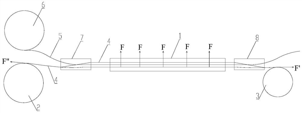
[0051] Such as Figure 3 to Figure 11 As shown, the second embodiment provides the second embodiment of the conveying device for laying cables through pipes of the present invention. The second embodiment is basically the same as the first embodiment, and the similarities will not be repeated. The difference is that in the second embodiment, when the conveyor belt 4 is in contact with the cable 5, the cable 5 is partially or completely wrapped, thereby ensuring the transportation The stability of the belt 4 supporting the cables 5 enables the conveyor belt 4 to effectively drive the cables 5 through the pipe arrangement 1 together.

[0052] see Figure 4 , in the second embodiment, preferably, the conveyor belt 4 includes a first traction rope 41, a second traction rope 42 and a trawl net 43, and the first traction rope 41 and the second traction rope 42 are all connected to the take-up machine 3 and the pay-off machine 2. The trawl net 43 is fixed between the first traction...


PUM


Abstract

The invention relates to the technical field of cable laying, in particular to a conveying device for laying cables through pipes, including a pay-off machine, a wire take-up machine and a conveyor belt. Placed at the outlet of the pipe, one end of the conveyor belt is wound on the pay-off machine and the other end passes through the pipe and connected to the take-up machine. The take-up machine provides traction for the conveyor belt, and the cable is supported on the conveyor belt. It also relates to a method for laying cables through pipes, using the above-mentioned conveying device for laying cables through pipes, the conveyor belt provides support for the cables in the pipes, and the cables are driven through the pipes together under the traction of the wire take-up machine. The conveyor belt provides uninterrupted and continuous support for the cable in the pipe, and can provide all or most of the power required for the cable to pass through the pipe in a straight or approximately straight line, reducing the main traction required for the cable to pass through the pipe , so as to reduce the side pressure at the corner, and also reduce the number of required conveyors and corresponding underground wells.

Description

technical field [0001] The invention relates to the technical field of cable laying, in particular to a conveying device for laying cables through pipes and a method for laying cables through pipes. Background technique [0002] Large cross-section power cables have large cross-sectional area and heavy weight per unit length, such as cables with voltage levels above 220kV, superconducting cables, etc. The laying process of such cables is usually suitable for trench and tunnel environments. Due to the narrow space in the city, when cable pipes have to be used for laying, the weight per unit length of the large cross-section power cables causes a large friction force between them and the wall of the cable pipes, which corresponds to the traction force in the required pipe laying process And the side pressure at the corner is relatively large, and the cable body has strict restrictions on the traction force and side pressure it bears, otherwise the structure of the cable body w...

Claims


Application Information

Patent Timeline
Patent Type & Authority Patents(China)
IPC IPC(8): H02G1/08
CPCH02G1/083
Inventor 宗曦华张喜泽张大义喻志广张智勇韩云武魏士政高原
Owner SHANGHAI INT SUPERCONDUCTION TECH CO LTD
Why Eureka
Try Eureka