
Cutting stapling device

A stapler and staple cartridge technology, which is applied in the field of medical devices, can solve the problems of difficult operation and unstable operation of staple cartridges and staplers, and achieves the effects of simple and convenient plug-in assembly and stable operation.

Active Publication Date: 2020-08-11
MICONVEY TECH CO LTD
View PDF7 Cites 4 Cited by
  • Summary
  • Abstract
  • Description
  • Claims
  • Application Information

AI Technical Summary

Problems solved by technology

[0004] In view of the above-mentioned shortcomings of the prior art, the purpose of the present invention is to provide a cutting and stapling device for solving the problems in the prior art that the operation is difficult when the nail magazine is inserted into the stapler, and the operation is unstable after insertion.

Method used


Image

  • Cutting stapling device
  • Cutting stapling device
  • Cutting stapling device

Examples


Embodiment Construction

[0037] Embodiments of the present invention are described below through specific examples, and those skilled in the art can easily understand other advantages and effects of the present invention from the content disclosed in this specification. The present invention can also be implemented or applied through other different specific implementation modes, and various modifications or changes can be made to the details in this specification based on different viewpoints and applications without departing from the spirit of the present invention.

[0038] It should be noted that the diagrams provided in this embodiment are only schematically illustrating the basic idea of ​​the present invention, and only the components related to the present invention are shown in the diagrams rather than the number, shape and shape of the components in actual implementation. Dimensional drawing, the type, quantity and proportion of each component can be changed arbitrarily during actual impleme...


PUM


Abstract

The invention relates to the field of medical instruments, in particular to a cutting stapling device. The cutting stapling device comprises a staple box, a stapler, a staple box steering connecting rod assembly and a stapler steering connecting rod assembly, wherein a staple box locking bump is arranged on a staple box cover assembly of the staple box; the two ends of the staple box steering connecting rod assembly are connected with a bent head of the staple box and a stapler steering connecting rod respectively; the stapler is provided with an stapler gun barrel inner core and a two-way drive rotating mechanism connected with the stapler steering connecting rod; the inner side wall of the stapler gun barrel inner core is provided with a guide surface, a guide groove matched with a clamping block and a locking groove matched with the staple box locking bump; the clamping block slides to a preset position along the guide groove and rotates to be connected with the stapler steering connecting rod assembly; and the two-way drive rotating mechanism rotates for enabling the bent head to be bent. The cutting stapling device has the beneficial effects that the staple box and the staplerare inserted and assembled more simply and conveniently, and the bent head is driven to be bent through the two-way drive rotating mechanism, so that the bent head runs more stably.

Description

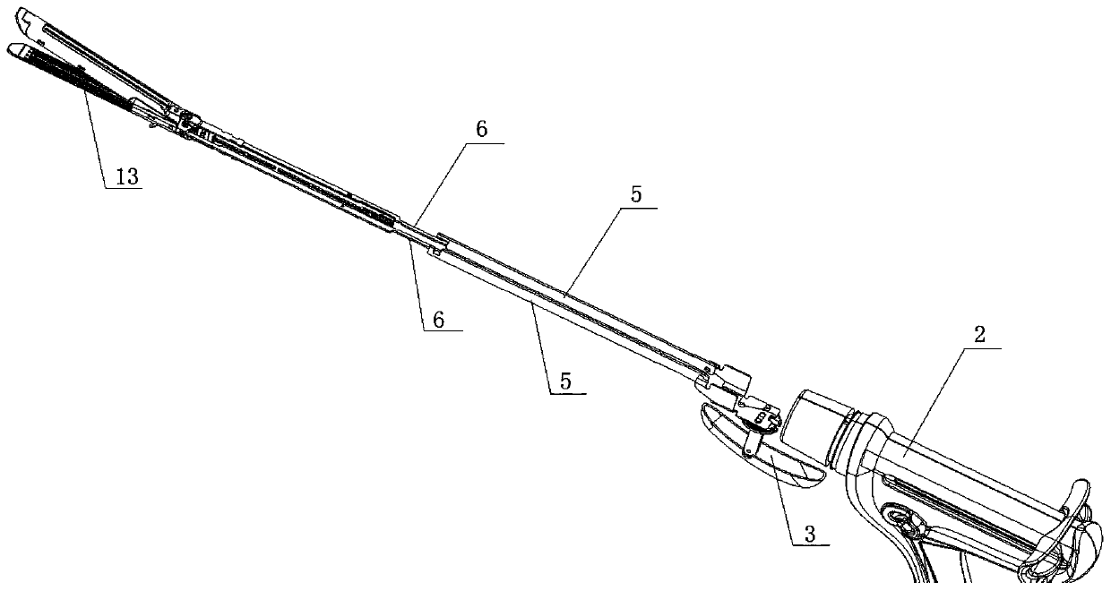
technical field [0001] The invention relates to the field of medical instruments, in particular to a cutting and stapling device. Background technique [0002] like figure 1 As shown, the cutting and stapling device generally includes a stapler 2 and a stapler 1. When the existing stapler 2 and the stapler 1 are inserted and connected, it is necessary to accurately perform alignment and insertion according to the arrow marks on the stapler and the stapler, and Insertion can only be performed in this one orientation. After the insertion is completed, the stapler 1 and the steering knob 3 of the stapler 2 form a fixed geometric relationship, thereby limiting the scope of application of the cutting and stapling device and the operation of the doctor during surgery. [0003] The stapler 1 and the stapler 2 that have been inserted are connected by the stapler steering link 5 and the nail box steering link 6, wherein the first end of the stapler steering link 5 is connected by th...

Claims


Application Information

Patent Timeline
IPC IPC(8): A61B17/072
CPCA61B17/07207A61B2017/07221A61B2017/07271A61B2017/07285
Inventor 董宇国
Owner MICONVEY TECH CO LTD
Learn More