
A plastic mechanically dyed structure

A technology of plastic machinery and vertical mixer, applied in the field of dyeing structure, can solve the problems of agglomeration of plastic particles, large gaps, leakage of dyeing agent, etc., and achieve the effect of convenient efficient stirring and clean dyeing.

Active Publication Date: 2021-09-28
山东诺森塑胶有限公司
View PDF0 Cites 0 Cited by
  • Summary
  • Abstract
  • Description
  • Claims
  • Application Information

AI Technical Summary

Problems solved by technology

[0002] In the dyeing of plastics, the plastic particles are generally stirred and mixed by a vertical mixer, so that the plastic particles and the dye are evenly mixed. It is widely used in plastic dyeing factories and has a good use effect. The existing The stirring device for plastic dyeing cannot meet people's needs, and the existing stirring device for plastic dyeing mainly has the following disadvantages when in use:
[0003] 1. When dyeing plastic particles, in order to facilitate the opening of the top cover of the vertical mixer, the motor will generally be set at the bottom to drive the stirring rod to rotate. In traditional devices, bearings are generally used to ensure that the main shaft and the mixer The rotation between them is interspersed, but the gap between the two shaft sleeves of the general bearing is large, and the dye is easy to leak through the gap, which will cause the leakage of the dye
[0004] 2. When the dyeing of plastic particles is completed, if a part of the dyed plastic sticks together for a long time, it is easier to cause agglomeration between the plastic particles, thus causing the plastic discharge pipe to be blocked

Method used

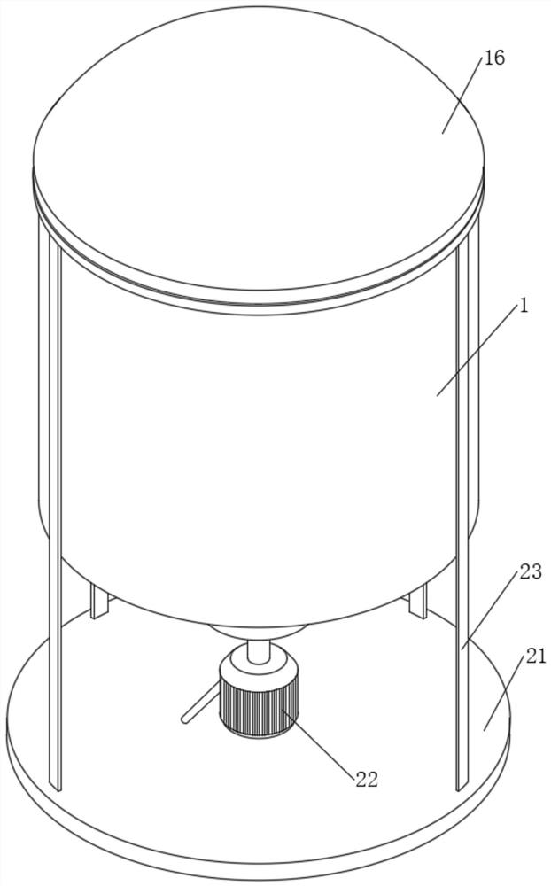
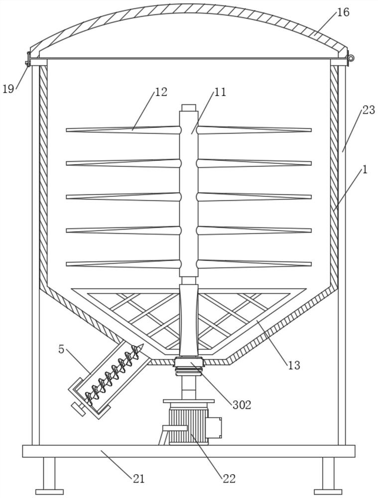
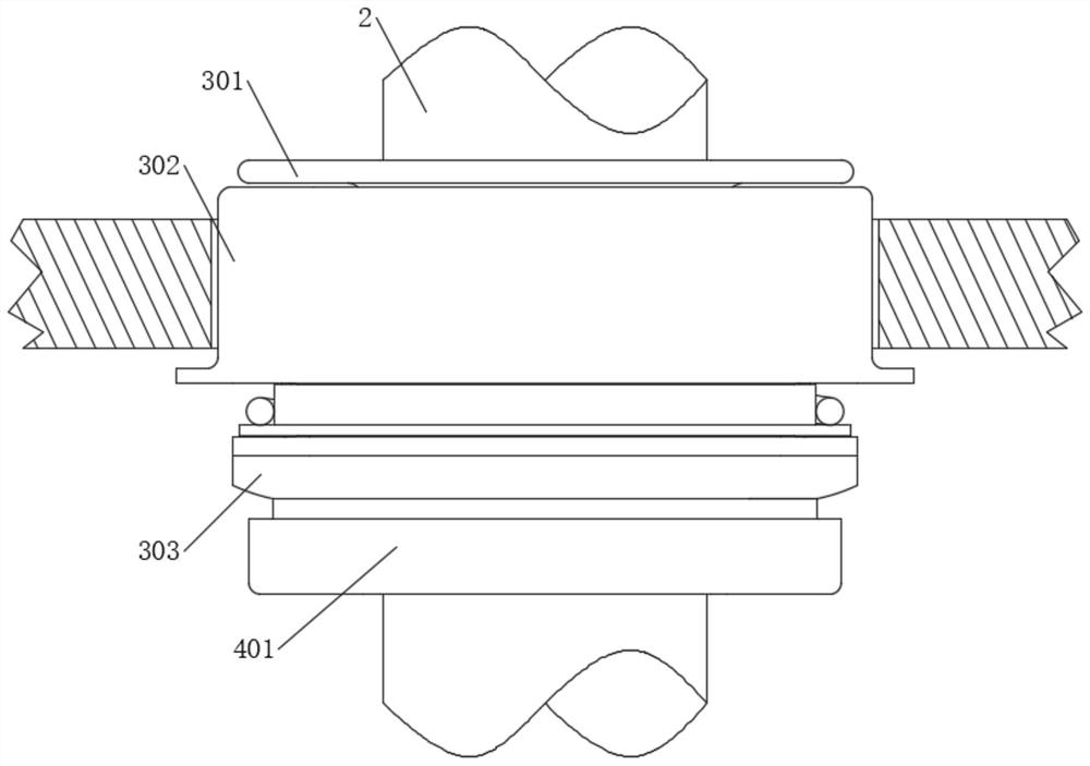

Image

  • A plastic mechanically dyed structure
  • A plastic mechanically dyed structure
  • A plastic mechanically dyed structure

Examples


Embodiment Construction

[0028] The following will clearly and completely describe the technical solutions in the embodiments of the present invention with reference to the accompanying drawings in the embodiments of the present invention. Obviously, the described embodiments are only some, not all, embodiments of the present invention. Based on the embodiments of the present invention, all other embodiments obtained by persons of ordinary skill in the art without making creative efforts belong to the protection scope of the present invention.

[0029] The present invention provides such as Figure 1-7 The shown plastic mechanical dyeing structure includes a vertical mixer housing 1 , and a main shaft 2 is arranged in the inner cavity of the vertical mixer housing 1 .

[0030] The bottom of the outer wall of the main shaft 2 is fixedly sleeved with a first shaft sleeve 301, and the shape of the first shaft sleeve 301 is a T-shaped ring structure, which is convenient for the lower surface of the first ...


PUM


Abstract

The invention discloses a plastic mechanical dyeing structure, which comprises a vertical mixer housing, in which a main shaft is arranged, the bottom of the outer wall of the main shaft is fixedly sleeved with a first shaft sleeve, and the outer sleeve of the first shaft sleeve A fixed sleeve is provided, and the fixed sleeve is fixedly sleeved on the bottom of the vertical mixer shell. The bottom of the fixed sleeve is sleeved with a second bushing, and the outer fixed sleeve of the second bushing is connected with a first connecting ring. The first spring A spring is arranged between the seat and the second spring seat, the middle part of the connecting cylinder cover is rotated and connected with a rotating rod, and an auger is arranged on the outside of the rotating rod. The present invention utilizes the cooperating arrangement of the first shaft sleeve and the fixed sleeve to keep the first shaft sleeve and the fixed sleeve in close contact with each other so as to prevent leakage of the dyeing agent, thereby making the dyeing of plastic particles cleaner and cleaner. The dragon will take out the plastic particles, so that the blocked inner cavity of the discharge pipe can be dredged, so as to continue the discharge work of the discharge pipe.

Description

technical field [0001] The invention relates to the field of dyeing structures, in particular to a plastic mechanical dyeing structure. Background technique [0002] In the dyeing of plastics, the plastic particles are generally stirred and mixed by a vertical mixer, so that the plastic particles and the dye are evenly mixed. It is widely used in plastic dyeing factories and has a good use effect. The existing The stirring device for plastic dyeing cannot meet people's needs, and the existing stirring device for plastic dyeing mainly has the following disadvantages when in use: [0003] 1. When dyeing plastic particles, in order to facilitate the opening of the top cover of the vertical mixer, the motor will generally be set at the bottom to drive the stirring rod to rotate. In traditional devices, bearings are generally used to ensure that the main shaft and the mixer The rotation between them is interspersed, but the gap between the two shaft sleeves of the general bearin...

Claims


Application Information

Patent Timeline
Patent Type & Authority Patents(China)
IPC IPC(8): B05C11/00
CPCB05C3/08
Inventor 杨艳董英山
Owner 山东诺森塑胶有限公司
Learn More