Cleaning device for computer keyboard

A technology for cleaning devices and computers, which is applied to cleaning methods using tools, cleaning methods using gas flow, cleaning methods and utensils, etc., can solve the problems of falling internal impurities, inability to effectively clean keycaps, inconvenient inversion, etc. To achieve the effect of simple and convenient operation, better cleaning effect, and removal of sweat and oil stains

Active Publication Date: 2020-08-11
ANQING NORMAL UNIV
View PDF5 Cites 8 Cited by
  • Summary
  • Abstract
  • Description
  • Claims
  • Application Information

AI Technical Summary

Problems solved by technology

[0003] However, the existing computer keyboard does not have an automatic cleaning device. After impurities enter the interior, the user often turns it upside down, then knocks the back of the keyboard or directly bumps it against the work surface, so that the internal impurities fall, and then cleans it with a towel or Wipe the surface buttons with a damp cloth to remove the dust accumulated on the surface. This cleaning method has the following disadvantages: 1. The cleaning efficiency is low through manual cleaning by the operator; When wiping, it is inconvenient to keep turning it upside down, so the keyboard can only be placed upright on the work surface. At this time, since there are sweat or oil stains on the surface of the keys, it needs to be wiped with a towel or damp cloth with cleaning liquid. Cleaning fluid and water can easily enter the keyboard through the gaps of the keys, causing secondary damage to the keyboard; 3. It can only wipe the surface of the keyboard and keycaps, but the shell part of the keyboard that removes the keycaps is completely ineffective Cleaning, while the side end of a single keycap on the keyboard can not be cleaned effectively

Method used


Image

  • Cleaning device for computer keyboard
  • Cleaning device for computer keyboard
  • Cleaning device for computer keyboard

Examples


Embodiment Construction

[0026] In order to make the technical means, creative features, goals and effects achieved by the present invention easy to understand, the present invention will be further described below in conjunction with specific embodiments.

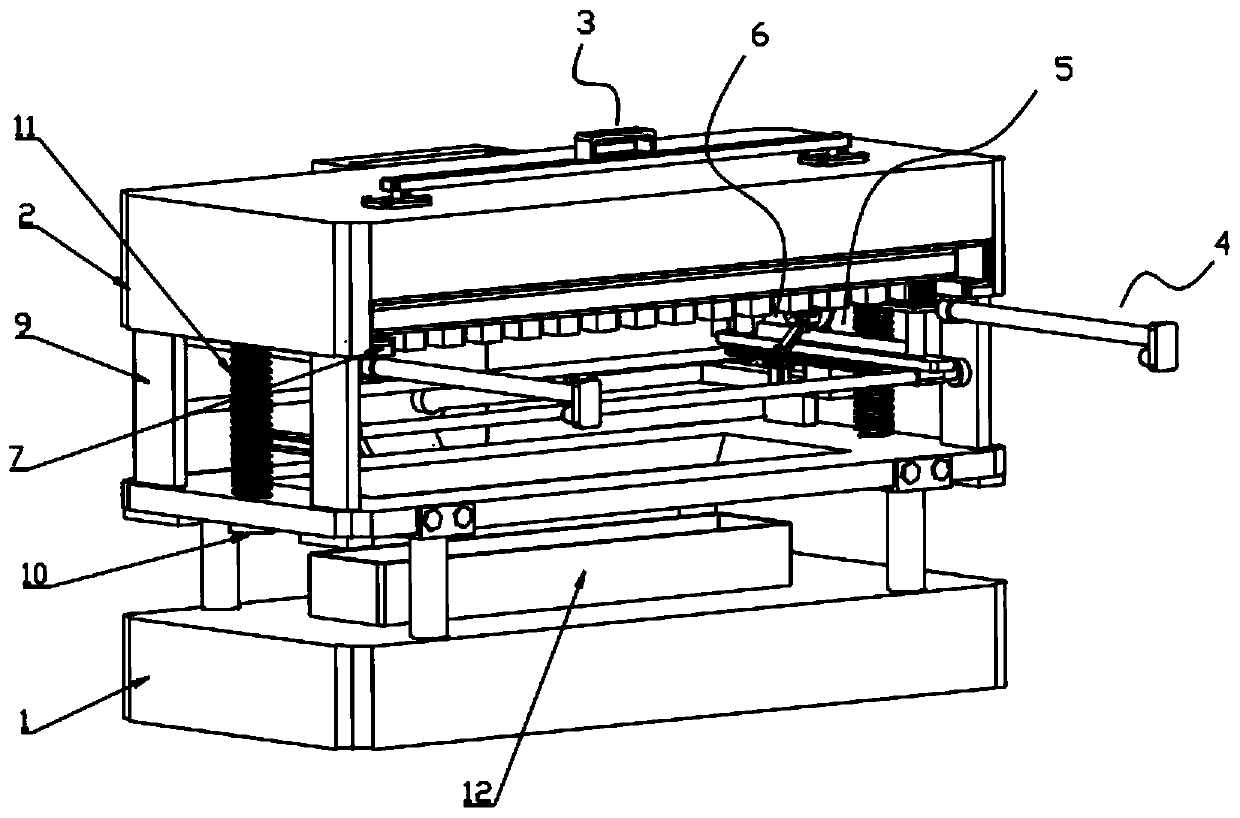
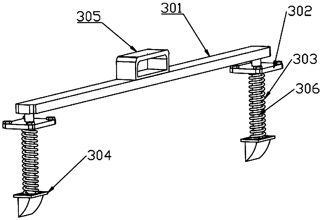
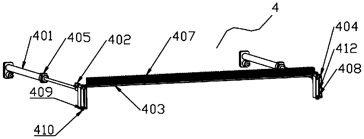
[0027] Such as Figure 1 to Figure 10 As shown, a cleaning device for a computer keyboard includes a frame 1, a mounting frame 2, a positioning mechanism 3, a longitudinal cleaning mechanism 4, a horizontal cleaning mechanism 5 and a cap cleaning mechanism 6, and the mounting frame 2 is installed on the frame 1, the mounting frame 2 is a hollow structure and the lower end is provided with two symmetrically arranged mounting rails 7, and the upper end of the mounting frame 2 is provided with two symmetrically arranged mounting cavities 8, and the lower end of the mounting frame 7 is fixed with two Symmetrically arranged and slidably arranged on the guide plate 9 on the frame 1, the lower end of the mounting rail 7 is also provided with a sliding co...


PUM


Abstract

The invention discloses a cleaning device for a computer keyboard, and relates to the technical field of computer hardware cleaning. The cleaning device comprises a rack, a mounting frame, a positioning mechanism, a longitudinal cleaning mechanism, a transverse cleaning mechanism and a cap cleaning mechanism, wherein the mounting frame is mounted at the upper end of the rack, the mounting frame isof a hollow structure, the lower end of the mounting frame is provided with two symmetrically-arranged laying rails, two symmetrically-arranged mounting cavities are formed in the upper end of the mounting frame, and two corresponding symmetrically-arranged guide plates arranged on the rack in a sliding mode are fixed to the lower end of each laying rail. The cleaning device is convenient to operate, sweat stains and oil stains attached to the surfaces of keys are effectively removed through the arrangement of the longitudinal cleaning mechanism and the inverted arrangement of the keyboard, meanwhile, cleaning liquid and clear water on a towel or wet cloth are prevented from entering the keyboard, through the arrangement of the transverse cleaning mechanism and the cap cleaning mechanism,bidirectional cleaning operation is automatically conducted on the keyboard, the positions where keycaps are removed can be cleaned, and the keycaps can be further cleaned.

Description

technical field [0001] The invention relates to the technical field of computer hardware cleaning, in particular to a cleaning device for computer keyboards. Background technique [0002] In the current era of Internet popularization, computers play an important role that cannot be ignored in our production, life and office. As an indispensable part of the computer hardware system, the keyboard is used to Corresponding instructions are input inside it. During long-term use, it is often found that impurities enter the interior, resulting in the phenomenon of key connection or key failure. From this point of view, regular maintenance is carried out to ensure the normal operation of the computer. Work is even more important. [0003] However, the existing computer keyboard does not have an automatic cleaning device. After impurities enter the interior, the user often turns it upside down, then knocks the back of the keyboard or directly bumps it against the work surface, so th...

Claims


Application Information

Patent Timeline
Patent Type & Authority Applications(China)
IPC IPC(8): B08B1/00B08B5/04B08B13/00
CPCB08B1/002B08B1/008B08B5/04B08B13/00
Inventor 周佳骏袁五一赵浩宇桂佳吴姗姗
Owner ANQING NORMAL UNIV
Why Eureka
Try Eureka