Rotary lifting mechanism of automatic welding auxiliary frame

An automatic welding, rotating and lifting technology, applied in the direction of welding/cutting auxiliary equipment, auxiliary devices, welding equipment, etc., can solve the problems of limited effect, poor accuracy of lateral movement position, and inability to accurately control the lateral movement interval, etc., to achieve convenient adjustment , the effect of high adjustment accuracy

Inactive Publication Date: 2020-08-11
台州市清引环保科技有限公司
View PDF7 Cites 0 Cited by
  • Summary
  • Abstract
  • Description
  • Claims
  • Application Information

AI Technical Summary

Problems solved by technology

[0002] The auxiliary frame of the existing automatic welding mechanism can generally adjust the height of the welding head up and down, and when the welding head moves, it is generally pushed by the cylinder to realize slow movement, and the accuracy of its lateral movement position is poor and cannot be accurately controlled Its lateral movement range has limited effect

Method used


Image

  • Rotary lifting mechanism of automatic welding auxiliary frame
  • Rotary lifting mechanism of automatic welding auxiliary frame
  • Rotary lifting mechanism of automatic welding auxiliary frame

Examples


Embodiment Construction

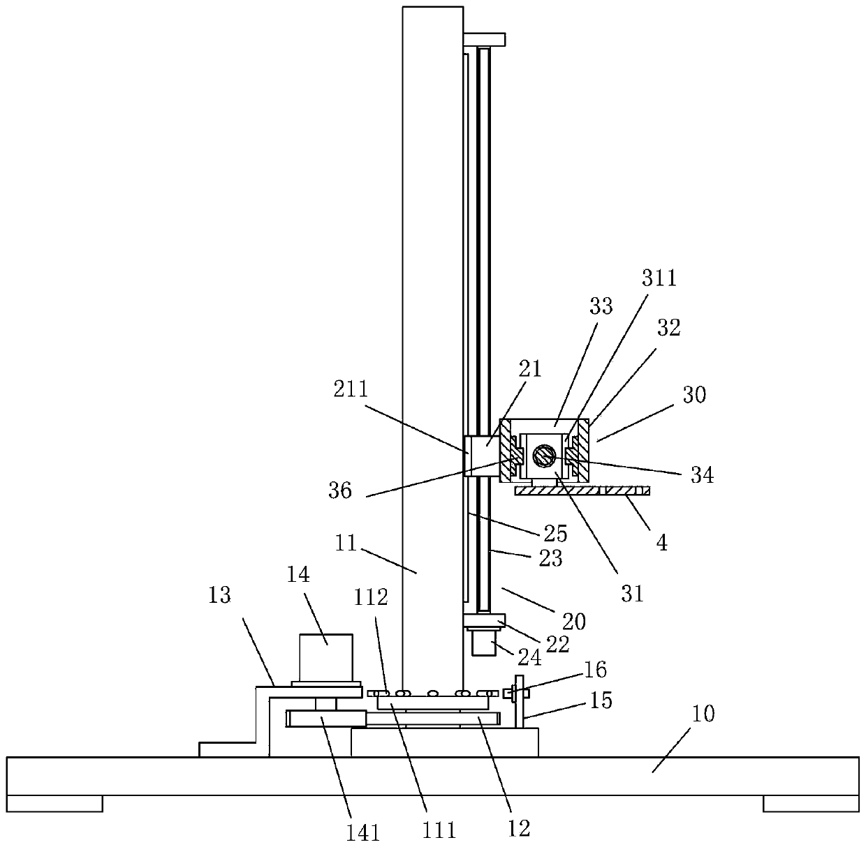
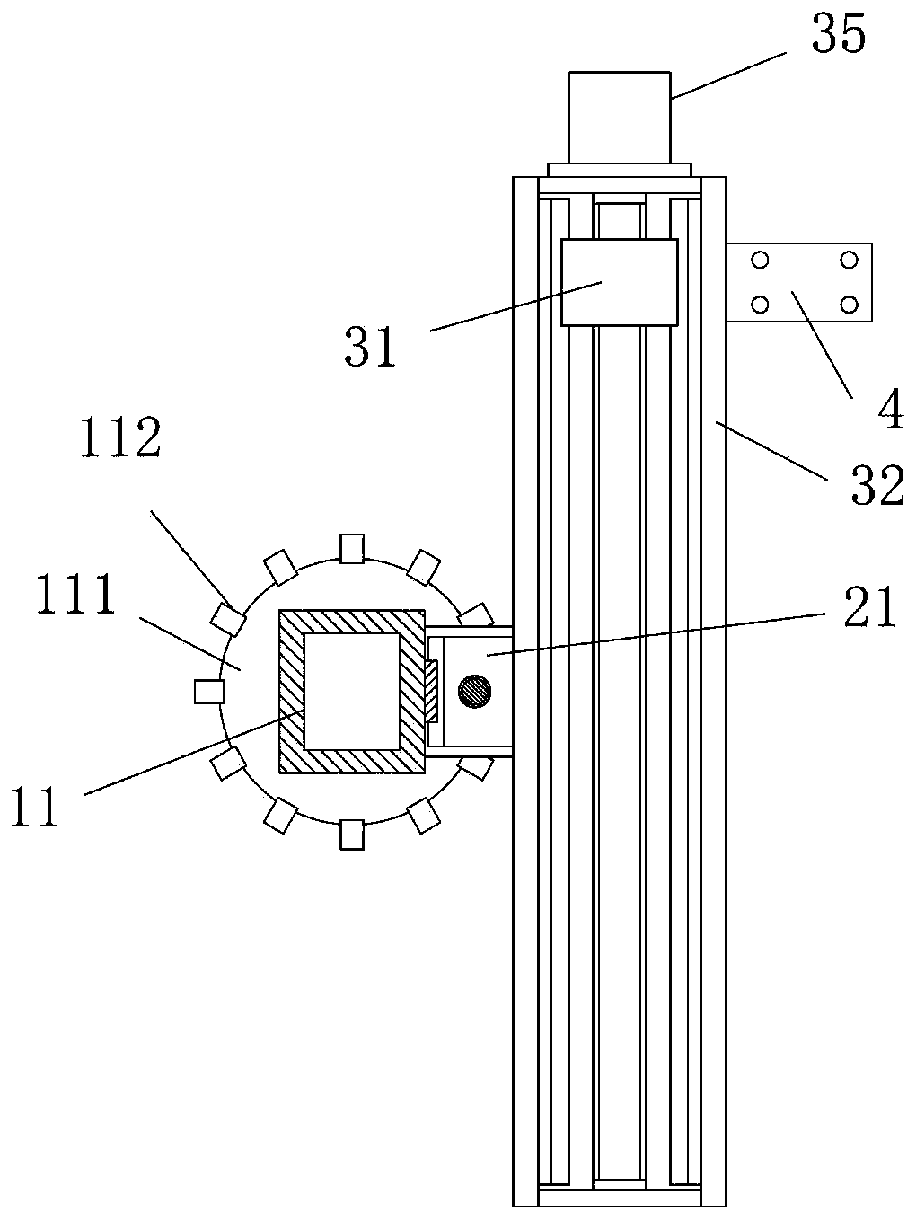
[0017] Examples, see e.g. Figure 1 to Figure 3 As shown, a rotary lifting mechanism of an automatic welding auxiliary frame includes a fixed base 10, the middle part of the top surface of the fixed base 10 is hinged with a vertical main rod 11 through a bearing, and the bottom end of the vertical main rod 11 is fixed with a transmission gear 12. A support frame 13 is fixed on one side of the top surface of the fixed base 10, a rotary servo motor 14 is fixed on the top surface of the top plate of the support frame 13, and the output shaft of the rotary servo motor 14 passes through the bottom surface of the top plate of the support frame 13 and is fixed There is a driving gear 141, and the driving gear 141 is meshed with the transmission gear 12;

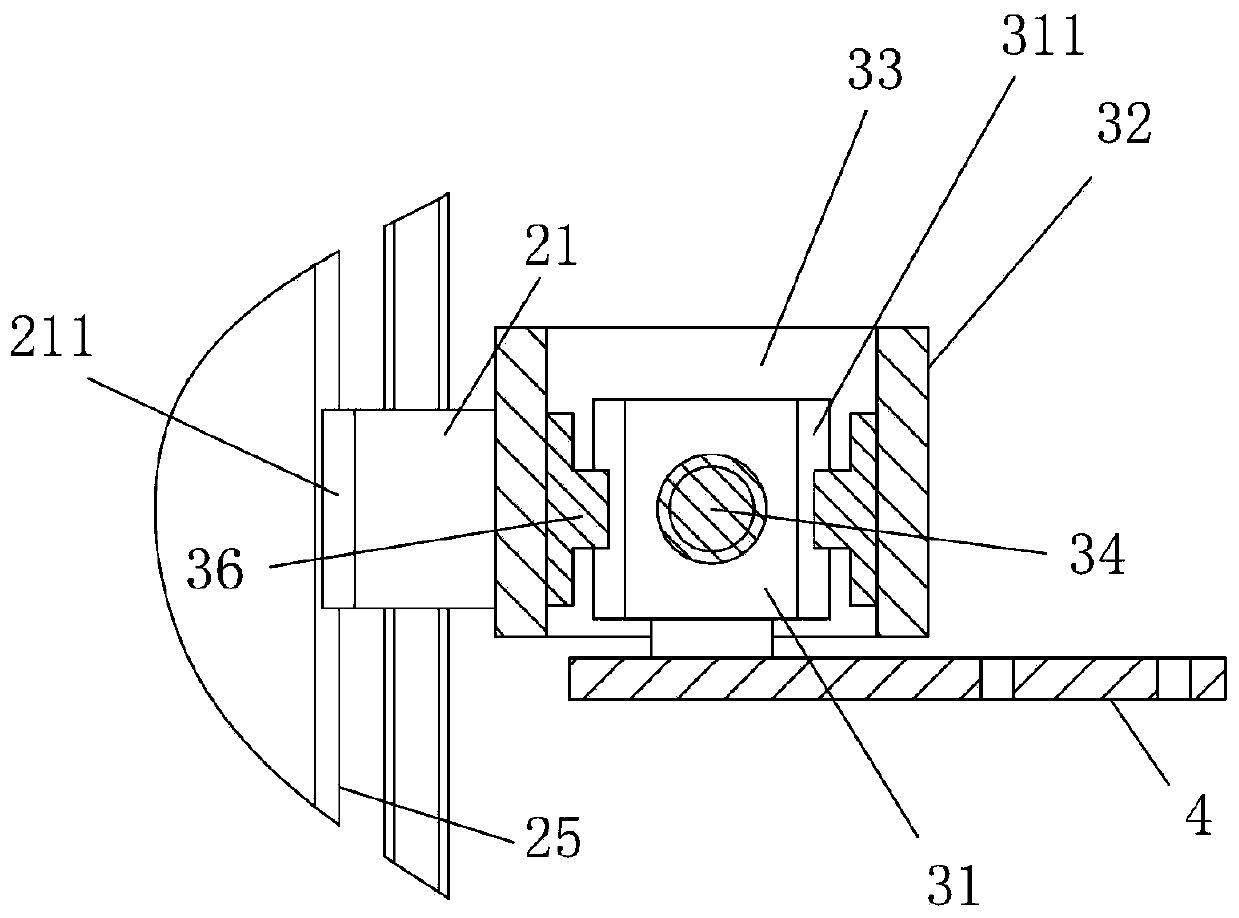
[0018] One side of the vertical main rod 11 is fixed with a vertical lifting mechanism 20, the lifting block 21 of the vertical lifting mechanism 20 is fixed with a lateral moving mechanism 30, and the bottom surface of the main mov...


PUM


Abstract

The invention discloses a rotary lifting mechanism of an automatic welding auxiliary frame. The rotary lifting mechanism comprises a fixed base, wherein a vertical main rod is hinged to the middle ofthe top surface of the fixed base through a bearing; a transmission gear is fixed at the bottom end of the vertical main rod; a supporting frame is fixed on one side of the top surface of the fixed base; a rotary servo motor is fixed on the top surface of a top plate of the supporting frame; an output shaft of the rotary servo motor penetrates through the bottom surface of the top plate of the supporting frame and is fixedly provided with a driving gear; the driving gear is meshed with the transmission gear; and a vertical lifting mechanism is fixed on one side of the vertical main rod, and atransverse moving mechanism is fixed on a lifting block of the vertical lifting mechanism. According to the rotary lifting mechanism, a welding head can be installed on a lower connecting horizontal plate, the vertical height adjustment and the transverse position adjustment can be realized, the adjustment is convenient, the adjustment is realized by adopting the rotation of a vertical adjusting screw rod and a transverse adjusting screw rod, the adjusting precision is high, and the movement adjustment in a specific interval can be realized.

Description

technical field [0001] The invention relates to the technical field of mechanical processing equipment, in particular to a rotary lifting mechanism for an automatic welding auxiliary frame. Background technique [0002] The auxiliary frame of the existing automatic welding mechanism can generally adjust the height of the welding head up and down, and when the welding head moves, it is generally pushed by the cylinder to realize slow movement, and the accuracy of its lateral movement position is poor and cannot be accurately controlled Its lateral movement interval has limited effect. Contents of the invention [0003] The purpose of the present invention is to overcome the deficiencies of the prior art and provide a rotary lifting mechanism for the automatic welding auxiliary frame, which can install the welding head on the lower connecting horizontal plate, which can realize the up and down height adjustment and lateral position adjustment, and its adjustment is convenien...

Claims


Application Information

Patent Timeline
IPC IPC(8): B23K37/02
CPCB23K37/02B23K37/0211
Inventor 张小富
Owner 台州市清引环保科技有限公司
Why Eureka
Try Eureka