Textile material positioning device
A material positioning and material technology, which is applied in the cutting of textile materials, textile and paper making, workpiece clamping devices, etc., can solve the problems such as inability to tilt and fix materials, so as to facilitate next processing, convenient positioning and clamping, and prevent cloth movement Effect
- Summary
- Abstract
- Description
- Claims
- Application Information
AI Technical Summary
Problems solved by technology
Method used
Image

Examples
specific Embodiment approach 1
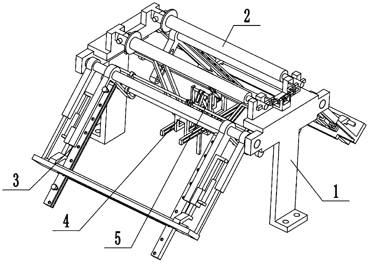
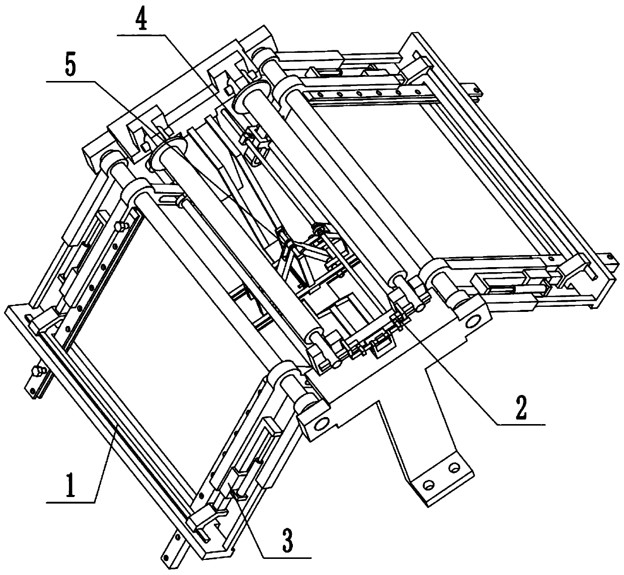
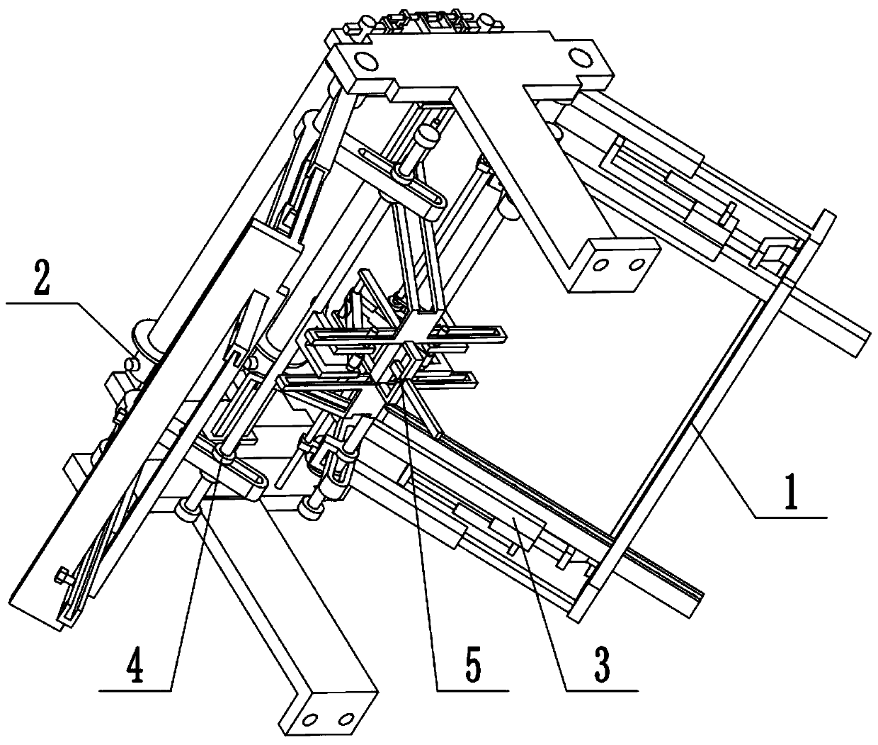
[0028] Combine below Figure 1-8Describe this embodiment, a textile material positioning device, including a fixed frame 1, a reel set frame 2, a material fixing mechanism 3, a width adjustment member 4 and an angle adjustment member 5, the reel set frame 2 is located on On the upper end of the middle part of the fixed frame 1, two material fixing mechanisms 3 are arranged, and the two material fixing mechanisms 3 are symmetrically arranged at both ends of the fixed frame 1, and two width adjusting parts 4 are provided, and the two width adjusting parts 4 are respectively connected with two The material fixing mechanism 3 is matched and connected, and the angle adjusting part 5 is fixedly connected to the middle part of the fixed frame 1, and the angle adjusting part 5 is connected with the two width adjusting parts 4; the angle adjusting part 5 is used to adjust the angle of the two material fixing mechanisms 3. When in use, set the rolled material on the reel set frame 2, st...
specific Embodiment approach 2
[0030] Combine below Figure 1-8 To illustrate this embodiment, the fixed frame 1 includes a top seat 1-1, an L-shaped leg 1-2, a fixed shaft 1-3, a hollow rod 1-4, a telescopic rod 1-5, a bottom plate 1-6, and a trapezoidal Bar 1-7 and rectangular slot 1-8; the lower ends of the two top seats 1-1 are respectively fixedly connected with an L-shaped outrigger 1-2, and the two top seats 1-1 are fixedly connected with two left and right fixed shafts 1 -3, the two fixed shafts 1-3 are respectively rotated to connect two hollow rods 1-4, the four telescopic rods 1-5 are respectively slidingly fitted and connected in the four hollow rods 1-4, and the left and right bottom plates 1-6 They are respectively fixedly connected to the two telescopic rods 1-5 on the left and right sides, and the inner sides of the two base plates 1-6 are respectively fixedly connected to a trapezoidal bar 1-7, and the two base plates 1-6 are respectively provided with a rectangular through slot 1-8; the r...
specific Embodiment approach 3
[0032] Combine below Figure 1-8 To illustrate this embodiment, the reel set frame 2 includes a rear fixed seat 2-1, a mandrel 2-2, a fixed rod 2-3, a front fixed seat 2-4, a screw seat 2-5, a first two-way Screw rod 2-6, L-shaped inserting rod 2-7 and inserting rod seat 2-8; Rear fixed seat 2-1 and front fixed seat 2-4 are respectively fixedly connected on two top seats 1-1, two mandrels 2-2 are respectively connected to the two ends of the rear fixed base 2-1 through hinge shaft rotation, and the front ends of the two mandrels 2-2 are fixedly connected to a fixed rod 2-3 respectively, and the two fixed rods 2-3 are respectively abutted on the The two ends of front fixed seat 2-4, screw rod seat 2-5 are fixedly connected on the front fixed seat 2-4, and the first two-way screw rod 2-6 is connected on the screw rod seat 2-5 in rotation, and two L-shaped insertion rods 2 -7 are respectively connected to the two ends of the first two-way screw rod 2-6 through thread fit, and th...
PUM
 Abstract
Description
Claims
Application Information
 - R&D
- Intellectual Property
- Life Sciences
- Materials
- Tech Scout
- Unparalleled Data Quality
- Higher Quality Content
- 60% Fewer Hallucinations
Browse by: Latest US Patents, China's latest patents, Technical Efficacy Thesaurus, Application Domain, Technology Topic, Popular Technical Reports.
© 2025 PatSnap. All rights reserved.Legal|Privacy policy|Modern Slavery Act Transparency Statement|Sitemap|About US| Contact US: help@patsnap.com