
Full-automatic composite hose making machine

A fully automatic, tube machine technology, applied to tubular objects, other household appliances, household appliances, etc., can solve the problems that the molding effect is difficult to maintain effectively and stably, cannot achieve continuous effect, and limits the production effect and production efficiency of composite hoses. , to achieve the effect of improving molding stability and improving production efficiency

Pending Publication Date: 2020-08-11
厦门市卓励石化设备有限公司 +1
View PDF0 Cites 5 Cited by
  • Summary
  • Abstract
  • Description
  • Claims
  • Application Information

AI Technical Summary

Problems solved by technology

[0003] Such a pipe-making method has the following defects: 1) the preparation length of the composite hose is limited to the length of the mandrel, which greatly limits the production effect and production efficiency of the composite hose; 2) the inner steel wire, cloth film, and The outer steel wire is sent to the rotating mandrel in a moving state for winding and forming, and the forming effect is difficult to maintain effectively and stably; 3) The inner steel wire feeding mechanism, cloth film output mechanism and outer steel wire feeding mechanism in the production process It needs to move back and forth constantly, and cannot achieve continuous effect, resulting in low overall production efficiency of composite hoses

Method used


Image

  • Full-automatic composite hose making machine
  • Full-automatic composite hose making machine
  • Full-automatic composite hose making machine

Examples


Embodiment Construction

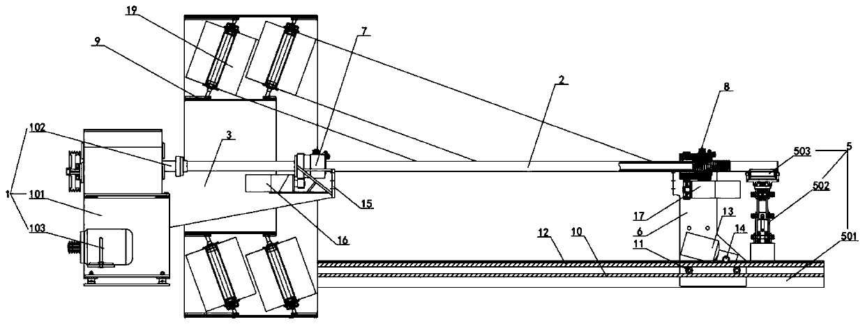
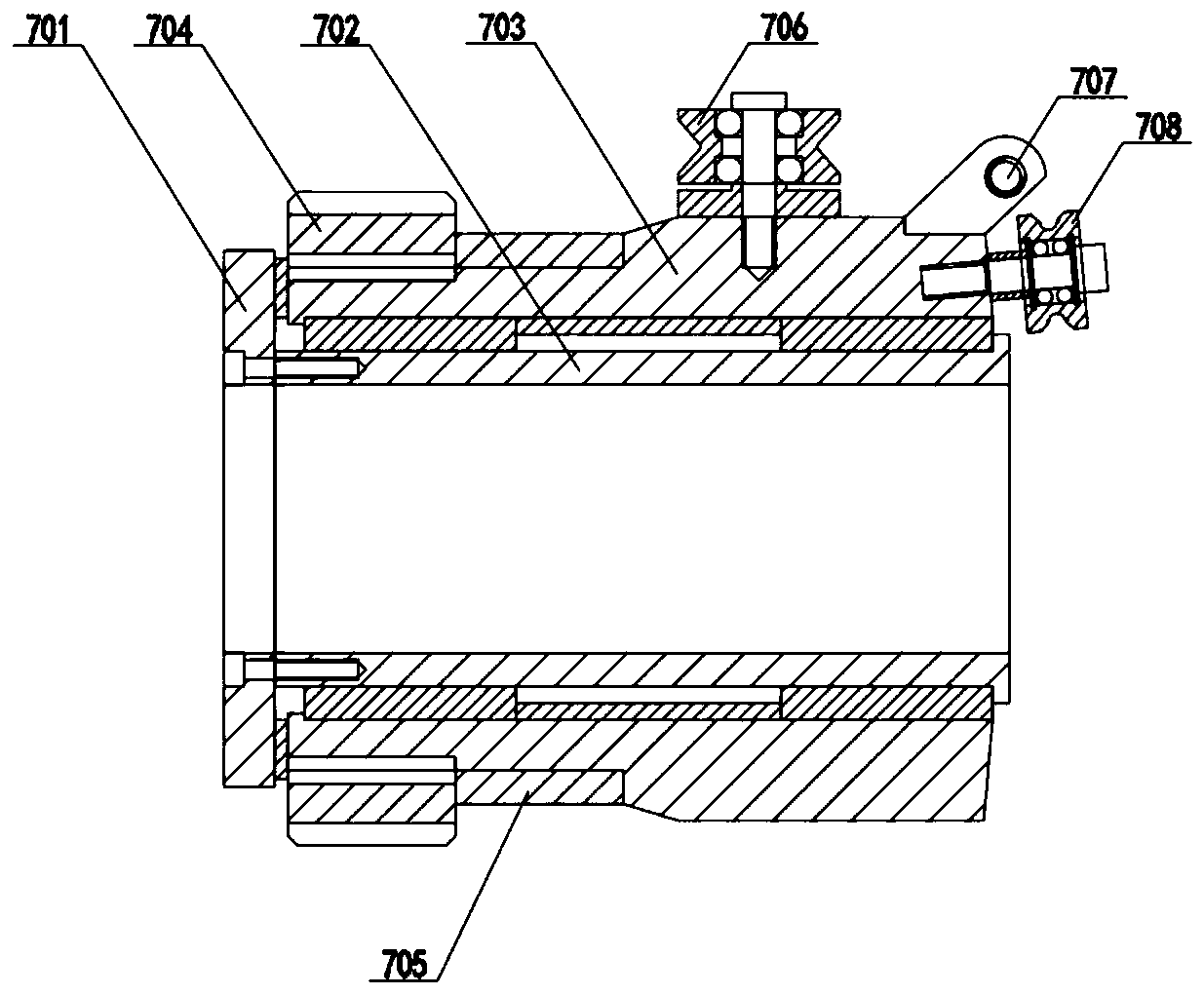
[0036] In order to facilitate the understanding of those skilled in the art, the structure of the present invention will be further described in detail with the embodiments and the accompanying drawings:

[0037] reference Figure 1-5 (For ease of presentation, figure 1 The base of the cloth film winding mechanism is not shown).

[0038] A fully automatic composite hose pipe making machine, including

[0039] The mandrel drive mechanism 1 is used to drive the mandrel mechanism 2. The mandrel drive mechanism 1 includes a mounting base 101, the upper part of the mounting base 101 is rotatably mounted with a drive shaft 102, and the drive shaft 102 is driven by a corresponding drive motor 103 for driving, the forward fixing device of the mounting seat 101 has an inner steel wire winding mechanism mounting plate 3;

[0040] The mandrel mechanism 2 is arranged on the front side of the mounting seat 101. The mandrel mechanism 2 includes a mandrel body 201 that is drive-connected to the dri...


PUM


Abstract

The invention relates to a full-automatic composite hose making machine. The full-automatic composite hose making machine comprises a core rod driving mechanism, a core rod mechanism, a supporting mechanism, an inner steel wire winding mechanism, an outer steel wire winding mechanism and a cloth film winding mechanism, wherein the core rod driving mechanism comprises a mounting base, and an innersteel wire winding mechanism mounting plate is fixedly arranged on the front portion of the mounting base; the core rod mechanism is arranged on the front side of the mounting base, the core rod mechanism comprises a core rod body in transmission connection with the core rod driving mechanism, the front end of the core rod body is fixedly connected with a tube removing core rod, and the tube removing core rod is provided with a tube removing thread; the supporting mechanism is arranged below the front side of the core rod body and comprises a bottom support, and an outer steel wire winding mechanism mounting plate is movably mounted on the bottom support; the inner steel wire winding mechanism is detachably arranged on the inner steel wire winding mechanism mounting plate; the outer steelwire winding mechanism is fixedly arranged on the outer steel wire winding mechanism mounting plate; and the cloth film winding mechanism is rotationally arranged at the rear end of the core rod body.According to the full-automatic composite hose making machine, the composite hose can be continuously prepared, and the forming stability of the composite hose can be effectively improved.

Description

Technical field [0001] The invention relates to a composite hose pipe making machine, in particular to a fully automatic composite hose pipe making machine. Background technique [0002] Composite hose is a kind of hose compounded by a variety of polymer materials. It has good flexibility and high safety. Therefore, composite hoses are widely used in highway and railway tank cars, warehouses, factories, docks and ships. Transmission, loading and unloading of oil and aromatic products. When preparing the composite hose, the existing composite hose pipe making machine mainly rotates through the mandrel mechanism. During the rotation of the mandrel, the inner steel wire threading mechanism, the cloth film output mechanism and the outer steel wire are moved. The threading mechanism sends the materials to the rotating mandrel evenly, and under the rotation of the mandrel, the inner ring steel wire winding, the cloth film winding and the outer ring steel wire winding are effectively c...

Claims


Application Information

Patent Timeline
Patent Type & Authority Applications(China)
IPC IPC(8): B29C70/32B29C70/54B29L23/00
CPCB29C70/32B29C70/54B29L2023/005
Inventor 宋恩以
Owner 厦门市卓励石化设备有限公司
Learn More