
An oil throwing structure in a transmission gearbox housing and its transmission

A technology for gearboxes and transmissions, which is applied in the directions of gear lubrication/cooling, belts/chains/gears, transmission parts, etc. It can solve problems such as increased kinetic energy loss, difficulty in obtaining lubrication, and increased weight of the transmission, so as to improve lubrication conditions, Simple structure and better lubricating effect

Active Publication Date: 2021-03-19
DONGFENG MOTOR CORP HUBEI
View PDF6 Cites 0 Cited by
  • Summary
  • Abstract
  • Description
  • Claims
  • Application Information

AI Technical Summary

Problems solved by technology

Differential gears and clutch gears are used as oil stirring gears to achieve splash lubrication in the box, but generator gears and drive motor gears are located at higher positions, making it difficult to get better lubrication
[0004] Active lubrication needs to add an additional oil pump as the driving mechanism of lubricating oil. Although it can achieve the ideal lubrication effect, it also brings the following major shortcomings: 1. After adding the oil pump, it will increase the kinetic energy loss and reduce the transmission. Overall transmission efficiency; 2. Many gears need to be arranged inside the transmission housing, and the space is very compact. Adding an oil pump and the corresponding oil guide plate groove structure will greatly increase the difficulty of the layout design of the transmission, and will also increase the weight of the transmission; 3 , Active lubrication In order to reduce the energy consumption of the oil pump, it is usually necessary to correspond the displacement of the oil pump to the working condition, which requires an additional control system, which not only increases the difficulty of design, but also is affected by the responsiveness and reliability of the oil pump There are also associated reliability risks to the transmission itself

Method used


Image

  • An oil throwing structure in a transmission gearbox housing and its transmission
  • An oil throwing structure in a transmission gearbox housing and its transmission
  • An oil throwing structure in a transmission gearbox housing and its transmission

Examples


Embodiment Construction

[0036]The present invention is further detailed in conjunction with the accompanying drawings and specific examples.

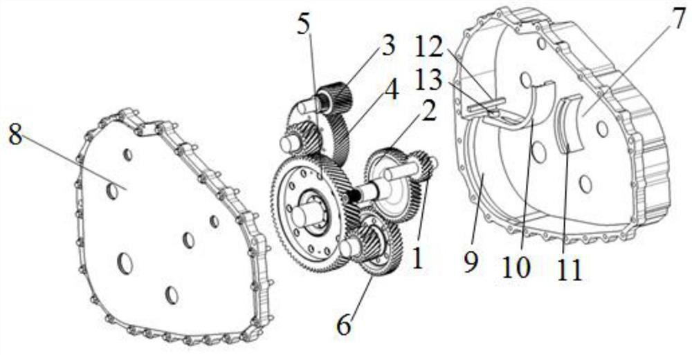
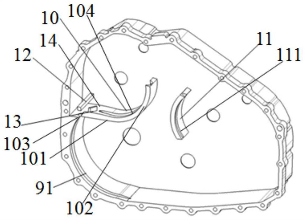
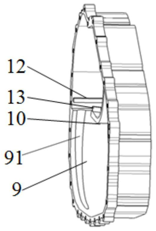
[0037]Such asFigure 1-9As shown, the present invention provides an oil structure in a transmission gearbox housing comprising a generator gear 1, an engine gear 2, a drive motor gear 3, an intermediate shaft gear 4, a differential gear 5, a clutch gear 6. The housing 7 and the housing cover 8 mounted with the housing 7, the inner wall of the housing 7 is provided with a first 甩 油 挡 9 having a lubrication gap between the differential gear 5, forming a lubrication gap between 4 intermediate shaft gears 4. The second oil baffle 10, the third 甩 油 挡 11 forms a lubrication gap between the engine gear 2; the first 甩 油 挡 板 9 extends upward from the minimum direction of the differential gear 5 to the second The oil baffle 10 is connected, and the second oil retaining plate 10 is provided with a oil mechanism to introduce a portion of the lubricating oil splashing from the first...


PUM


Abstract

The invention discloses an oil throwing structure in a transmission gear box shell and a transmission of the oil throwing structure. The oil throwing structure in the transmission gear box shell comprises a shell for accommodating a generator gear, an engine gear, a driving motor gear, an intermediate shaft gear, a differential gear and a clutch gear, and further comprises a shell cover matched with the shell; the oil throwing structure is characterized in that a first oil throwing baffle forming a lubricating gap with the differential gear, a second oil throwing baffle forming a lubricating gap with the intermediate shaft gear and a third oil throwing baffle forming a lubricating gap with the engine gear are arranged on the inner wall of the shell; and the first oil throwing baffle, the second oil throwing baffle and the third oil throwing baffle are provided with a first oil throwing groove, a second oil throwing groove and a third oil throwing groove which are used for increasing the oil throwing height correspondingly. According to the oil throwing structure, the structure is simple, the oil throwing grooves and the oil throwing baffles are arranged, the oil throwing height ofan oil stirring gear in the gravity direction can be increased without increasing the initial liquid level height of lubrication in the gearbox, and the transmission efficiency is improved.

Description

Technical field[0001]The present invention relates to the field of automotive transmission gearbox splashing technology, and specifically refers to an oil-proof structure and a transmission thereof in a gearbox housing.Background technique[0002]At present, most of the transmission is still using gear type, and the gear type transmission mainly relys with different gear ratios of the gear to change the speed of the drive wheel. In order to reduce the friction between the gears, it is necessary to form an oil film between the working surface of the gear to make the working surface relatively separated, thereby improving the work efficiency and service life of the gear mechanism. Usually, most of the automotive transmission lubrication system uses a splash lubricating, but for geometric dimensions, different drive shafts in the gravity direction are large, so that drive shaft gears and bearings in the higher position in gravity direction rely on splash lubrication The lubrication effec...

Claims


Application Information

Patent Timeline
Patent Type & Authority Patents(China)
IPC IPC(8): F16H57/04
CPCF16H57/0424F16H57/0457
Inventor 姚毅张文龙崔燕平王江涛尹曼莉
Owner DONGFENG MOTOR CORP HUBEI
Learn More