
Novel positioning rib detection device

A detection device and positioning rib technology, applied in the direction of measuring device, mechanical measuring device, using mechanical device, etc., can solve the problems of poor device adjustment effect, etc., and achieve the effect of efficient detection, flexible lifting, and improving detection efficiency

Inactive Publication Date: 2020-08-11
JIANGSU PROVINCIAL CONSTR GRP CO LTD
View PDF6 Cites 3 Cited by
  • Summary
  • Abstract
  • Description
  • Claims
  • Application Information

AI Technical Summary

Problems solved by technology

Although the device can realize the detection function of the positioning rib, the adjustment effect of the device during the detection process is poor, and it cannot realize the flexible telescopic adjustment effect according to the detection needs. Therefore, a new type of positioning rib detection device is now provided to solve the problem. The above technical issues

Method used


Image

  • Novel positioning rib detection device
  • Novel positioning rib detection device
  • Novel positioning rib detection device

Examples


Embodiment 1

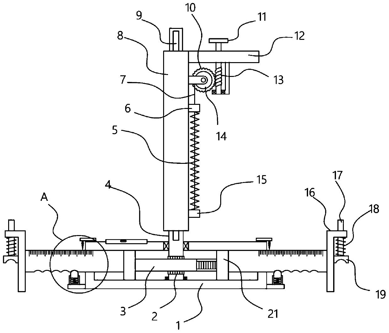
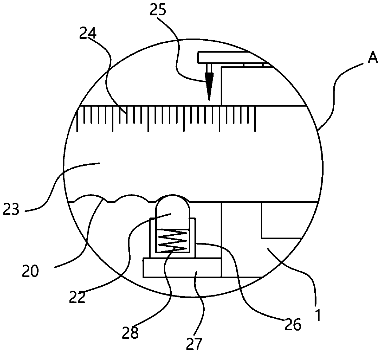
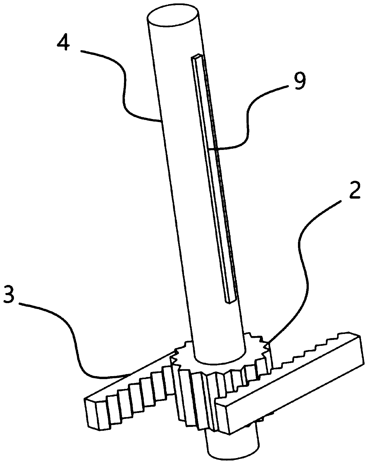
[0021] see Figure 1-3 , a new type of positioning rib detection device, including a transmission box 1, an adjustment sleeve 8 is vertically fixed on the transmission box 1, two symmetrically arranged telescopic rods 23 are slidably installed in the transmission case 1, and the ends of the telescopic rods 23 are fixed and useful For the clamping mechanism for clamping the positioning ribs, the transmission box 1 is provided with a telescopic mechanism for driving the telescopic rod 23 to slide. The adjustment sleeve 8 is sleeved with an adjustment sleeve 8, and the inner wall of the adjustment sleeve 8 is slidably embedded with a transmission clip 9 fixed on the side wall of the adjustment rotation rod 4. The adjustment sleeve 8 is fixed with a grip rod 12 , The grip rod 12 is provided with a lifting mechanism for driving the adjustment sleeve 8 to slide vertically relative to the adjustment rotating rod 4 .

[0022] The clamping mechanism set in this device is used to clamp...

Embodiment 2

[0028] On the basis of Embodiment 1, in addition, in addition, the clamping mechanism of the device includes an adjustment frame 16 fixed at the end of the telescopic rod 23, the adjustment frame 16 vertically slides through the guide column 17, and the bottom of the guide column 17 is fixed with an arc Block 19, the spring 18 that is sleeved on the guide post 17 is fixed between the arc block 19 and the adjustment frame 16, and the arc block 19 that is provided can clamp the positioning rib vertically downward, and press down under the elastic action of the spring 18. Tightly on the positioning rib, the arc groove provided at the bottom of the arc block 19 can play a limiting effect on the positioning rib.

[0029] In order to improve the adjustability of the device, the device is also provided with a lifting mechanism, including a fixed block 15 fixed on the side wall of the adjustment sleeve 8, and the side wall of the transmission clip 9 is fixed with a limiter that is vert...


PUM


Abstract

The invention discloses a novel positioning rib detection device, which relates to the technical field of positioning rib detection device. The positioning rib detection device comprises a transmission case, an adjusting sleeve is vertically fixed to the transmission case, a transmission clamping strip fixed to the side wall of an adjusting rotating rod is embedded in the inner wall of the adjusting sleeve in a sliding mode, a holding rod is fixed to the adjusting sleeve, and a lifting mechanism used for driving the adjusting sleeve to vertically slide relative to the adjusting rotating rod isarranged on the holding rod. Through the arranged clamping mechanism, the positioning rib can be clamped; the adjusting sleeve is rotated to drive the adjusting rotating rod to rotate; the transmission gear drives the two racks to move towards each other or away from each other, free telescopic adjustment of the telescopic rod is realized, and the arranged lifting mechanism can adjust the adjusting sleeve to vertically slide relative to the adjusting rotating rod, the height of the transmission box is adjusted, flexible lifting of the device is achieved according to the vertical position of the positioning rib needing to be detected, and the detection efficiency of the positioning rib is greatly improved.

Description

technical field [0001] The invention relates to the technical field of positioning rib detection, in particular to a novel positioning rib detection device. Background technique [0002] Before bridges or high-rise buildings, it may be required to drive piles under the foundation according to needs. When drilling piles, steel cages of different lengths are used. The length and diameter of the steel cages will be made according to the depth and diameter of the holes. During the production process In general, positioning ribs are welded every 2 meters, and four positioning ribs are welded around the steel bar. It is required to be made of first-grade steel with a diameter of 25, or second-grade rebar. The welding requirements are general, and positioning ribs can be added as needed during production. , in order to ensure the quality of the project, the positioning rib needs to be detected by the detection device after installation. [0003] Authorized announcement number is t...

Claims


Application Information

Patent Timeline
Patent Type & Authority Applications(China)
IPC IPC(8): G01B5/14G01B5/00
CPCG01B5/14G01B5/0002
Inventor 祝捷陈源源姬长玉常凯庆张允亮李国平周明柏李振伟罗建英王中凯邢政王兆军张贵星刘亚鸿张燕赵兴旺李亚光刘京超刘永林赵本超杨森池崇玉王俊斌
Owner JIANGSU PROVINCIAL CONSTR GRP CO LTD
Learn More