Sealed high-low voltage power distribution cabinet

A technology of high and low voltage power distribution cabinets, which is applied in the field of sealed high and low voltage power distribution cabinets, which can solve the problems of poor sealability of sealing rings, poor product shaping ability, high electrostatic current, etc., achieve good waterproof sealing and increase dustproof effect, the effect of increasing the service life

Active Publication Date: 2020-08-11
陕西西开仪表有限公司
View PDF3 Cites 4 Cited by
  • Summary
  • Abstract
  • Description
  • Claims
  • Application Information

AI Technical Summary

Problems solved by technology

[0004] 1. It is to prevent some exposed components in the cabinet from being covered by dust. If it is covered by dust and then absorbs moisture in the air, it will corrode some exposed components, which may lead to reduced insulation, short circuit, grounding, etc. for a long time malfunction, which may even result in the risk of electric shock
[0005] 2. Excessive dust coverage will lead to high electrostatic current in the case of humid air, which will also cause the risk of electric shock during operation, and excessive dust coverage will corrode the components of the box, which will also greatly Shorten the service life of components
However, the adsorbed dust will increase as time goes by, so it needs to be cleaned regularly, otherwise there will still be dust entering, which will also affect the effect of electrostatic dust removal
[0007] In addition, a sealing ring needs to be installed on the cabinet door. This sealing ring will age after a long time of use, and will also produce thermal deformation during use, resulting in poor sealing performance of the sealing ring. Aging is a common problem of all sealing rings, and thermal deformation will also cause The sealing performance of the sealing ring becomes poor. Since the sealing ring is an elastic part as a whole, it is prone to deformation and cannot be restored. The product has poor shaping ability and cannot maintain its shape for a long time.

Method used


Image

  • Sealed high-low voltage power distribution cabinet
  • Sealed high-low voltage power distribution cabinet
  • Sealed high-low voltage power distribution cabinet

Examples


Embodiment Construction

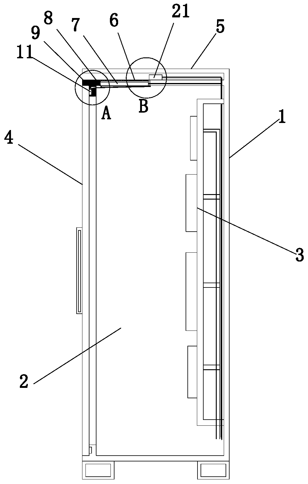
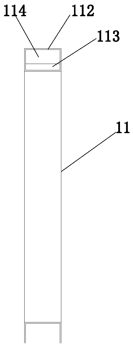
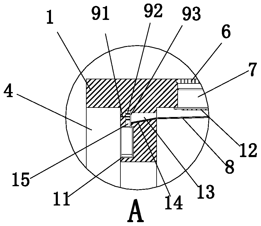
[0025] Such as figure 1 and Figure 4 As shown, the sealed high and low voltage power distribution cabinet includes a cabinet body 1, and a heat dissipation fan 7 is installed on the top of the cabinet body 1. The heat dissipation fan 7 draws the external air into the installation cavity 2 inside the cabinet body 1, and the The exhaust port at the bottom of the body 1 is discharged. The cabinet body 1 is provided with a cabinet door 4. A hollow silicone sealing ring 11 is embedded on the side of the cabinet body 1 facing the cabinet door 4. When the cabinet door 4 is closed, the cabinet door 4 and the slightly convex The silicone sealing ring 11 contacts the seal;

[0026] A filter screen 6 is installed on the top air inlet end of the cooling fan 7, and an electrostatic net 12 is installed on the air outlet end of the cooling fan 7, and an electrostatic generator 21 is installed on the top outer side of the cabinet body 1, and the electrostatic bar of the electrostatic genera...


PUM


Abstract

The invention discloses a sealed high-low voltage power distribution cabinet. The cabinet comprises a cabinet body, a heat dissipation fan is installed at the top of the cabinet body, the heat dissipation fan sucks external air into an installation cavity in the cabinet body and exhausts the external air from an exhaust port in the bottom of the cabinet body, the cabinet body is provided with a cabinet door, a hollow silica gel sealing ring is embedded in one surface, right opposite to the cabinet door, of the cabinet body, and after the cabinet door is closed, the cabinet door is in contact sealing with the slightly convex silica gel sealing ring; the power distribution cabinet not only has a very good dustproof effect, but also does not need to solve the problem of dust collection, the collected dust is used for filling the hollow silica gel sealing ring, the internal solid degree of the sealing ring is increased, thermal deformation of the sealing ring can be effectively prevented in the later period, the sealing effect is improved, and the sealing time is prolonged.

Description

technical field [0001] The invention relates to the field of power distribution cabinets, in particular to a sealed high and low voltage power distribution cabinet. Background technique [0002] Power distribution cabinets are commonly used power equipment and are used in many occasions. Since the power distribution cabinet is an electrical device, it needs to have very good dustproof and sealing capabilities: [0003] The importance of dust protection: [0004] 1. It is to prevent some exposed components in the cabinet from being covered by dust. If it is covered by dust and then absorbs moisture in the air, it will corrode some exposed components, which may lead to reduced insulation, short circuit, grounding, etc. for a long time malfunction, and may even result in the risk of electric shock. [0005] 2. Excessive dust coverage will lead to high electrostatic current in the case of humid air, which will also cause the risk of electric shock during operation, and excess...

Claims


Application Information

Patent Timeline
Patent Type & Authority Applications(China)
IPC IPC(8): H02B1/30H02B1/28
CPCH02B1/30H02B1/28
Inventor 廖计英
Owner 陕西西开仪表有限公司
Why Eureka
Try Eureka